eq. (10.19)
This model accounts for emissions when a liquid mixture is transferred into a vessel. It is used to compute VOC emissions by the following operations:
● Charge,
● Transfer In,
● Pull In and
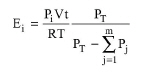
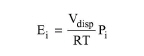
The model assumes that the displaced gas volume is equal to the volume of liquid transferred into the vessel. The receiving vessel may be empty or contain a liquid mixture from prior operations. The displaced gas is assumed to be saturated with VOC vapor at the exit temperature. According to this model, the amount of a component, i, emitted (in kmol) is calculated using the following equation:
|
|
eq. (10.19) |
where:
● Pi is the partial pressure of component i (in Pa),
● Vdisp is the volume of displaced gas (in m3),
● R is the ideal gas constant (8,314.5 J/kmol-K),
● T is the exit temperature (in K).
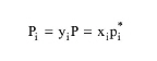
The partial pressure Pi is calculated by Raoult’s law:
|
|
eq. (10.20) |
where,
● xi is the mole fraction of component i in the liquid phase and
● pi* is its vapor pressure at temperature T (in Pa).
The vapor pressure, pi*, is calculated using Antoine’s equation or DIPPR’s special expression depending on whether the component properties are retrieved from the SuperPro Designer or DIPPR databases, respectively; for more details, see Thermodynamic Properties of Pure Components and Chapter 15 (Databases & Databanks).
For the calculation of uncontrolled emissions the temperature at which the component’s vapor pressure is calculated is set equal to the final temperature of the equipment contents (at the end of the respective operation). This temperature will, in general, be different than the temperature of the stream that is charged into the equipment as it is calculated by the energy balance of mixing the initial equipment contents with the charge stream. For the calculation of controlled emissions the temperature is set equal to the temperature of the condenser.
This model calculates the emissions when the pressure of a vessel is reduced. It is used to compute VOC emissions by the following operations:
● Evacuation,
● Purging / Inerting, and
● Venting.
Note that the model assumes that there is no leakage of air into the vessel even if the final pressure is below atmospheric. It is also assumed that there is no temperature change during the operation and that the displaced gas is saturated with VOC vapor(s) at the exit temperature of the vessel. Essentially, it is assumed that during the operation the total number of emitted moles in the gas space does not change (the emitted moles are replaced by the newly vaporized ones) and that the pressure change is entirely due to removal of inert gases. In consistency with the EPA-MACT guidelines for the calculation of depressurization emissions, SuperPro offers 3 alternative options.
Option 1
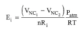
The amount of component i emitted (in kmol) is calculated using the following equation:
|
|
eq. (10.21) |
where,
● VNC1 and VNC2 are the initial and final volumes of the non-condensable components, respectively.
● Patm is the atmospheric pressure (in Pa),
● R is the ideal gas constant (8,314.5 J/kmol-K),
● T is the exit temperature (in K).
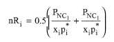
The term nRi in the above equation represents the average ratio of moles of non-condensable to moles of individual emitted components, calculated by:
|
|
eq. (10.22) |
where,
where,
● xi is the mole fraction of component i in the liquid phase and
● pi* is its vapor pressure at temperature T (in Pa).
Option 2
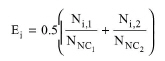
The amount of component i emitted (in kmol) is calculated using the following equation:
|
|
eq. (10.23) |
where,
● Ni,1 and Ni,2 are the initial and final moles of component i in the vapor phase. These are calculated by the ideal gas law at the initial and final pressure.
● NNC1 and NNC2 are the initial and final moles of non-condensables.
The above quantities are calculated by the ideal gas law at the initial and final pressure.
Option 3
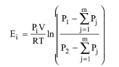
The amount of component i emitted (in kmol) is calculated using the following equation:
|
|
eq. (10.24) |
where:
● Pi is the partial pressure of component i (in Pa),
● V is the overhead volume of the vessel (in m3),
● R is the ideal gas constant (8,314.5 J/kmol-K),
● T is the exit temperature (in K).
● P1 and P2 are the initial and final pressures, respectively
The partial pressures of the emitted components Pi are calculated by Raoult’s law:
|
|
eq. (10.25) |
where,
● xi is the mole fraction of component i in the liquid phase and
● pi* is its vapor pressure at temperature T (in Pa).
The vapor pressure, pi*, is calculated using Antoine’s equation or DIPPR’s special expression depending on whether the component properties are retrieved from the SuperPro Designer or DIPPR databases, respectively; for more details, see Thermodynamic Properties of Pure Components and Chapter 15 (Databases & Databanks).
Notice that the sums of the partial pressures in the equation refer to the condensable components only.
This model accounts for emissions that are associated with sweeping a vessel with an inert gas (e.g., nitrogen). It is available in the Gas Sweep operation.
The model assumes that the sweeping gas leaves the system saturated with VOC vapor(s) at the exit (condenser) temperature. According to this model, the amount of component i emitted (in kmol) is calculated using the following equation:
|
|
eq. (10.26) |
where:
● Pi is the partial pressure of component i (in Pa),
● V is the purge flow rate at the temperature and pressure of the vessel vapor space (in m3/h),
● t is the purging time (in h),
● R is the ideal gas constant (8,314.5 J/kmol-K),
● T is the exit temperature (in K) and
● PT is the pressure of the vessel.
Notice that the sums of the partial pressures in the equation refer to the condensable components only.
The partial pressures of the emitted components Pi are calculated by Raoult’s law:
|
|
eq. (10.27) |
where,
● xi is the mole fraction of component i in the liquid phase and
● pi* is its vapor pressure at temperature T (in Pa).
The vapor pressure, pi*, is calculated using Antoine’s equation or DIPPR’s special expression depending on whether the component properties are retrieved from the SuperPro Designer or DIPPR databases, respectively; for more details, see Thermodynamic Properties of Pure Components and Chapter 15 (Databases & Databanks). If the purge flow rate is greater than 100 standard cubic feet per minute the values calculated by Raoult’s Law are multiplied by a factor of 0.25.
This model accounts for emissions that are associated with heating a vessel that contains a mixture of volatile components. It is available in the following operations:
● Batch Storage and
● Batch Storage (for Bulk Solids).
During heating under constant pressure, the gas of the vapor space undergoes expansion and a fraction leaves the vessel through the vent. Further, during heating there is an increase in the vapor pressure of VOC compounds. The removed gas (due to expansion) is assumed to be saturated in VOC vapor(s) at the average vessel temperature.
There are three available options for the calculation of heating emissions described below.
Option 1
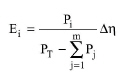
The amount of component i emitted (in kmol) is calculated from the following equation:
|
|
eq. (10.28) |
where:
● Pi is the partial pressure of component i (in Pa) at Tint = 0.5(T1 + T2),
● PT is the pressure of the vessel
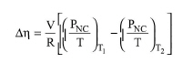
The moles of non-condensable components displaced, Δη, is calculated by the following equation:
|
|
eq. (10.29) |
where:
● PNC is the partial pressure of the non-condensable components
● T1 is the initial temperature of the system (in K) and
● T2 is the final temperature of the system (in K).
● R is the ideal gas constant (8,314.5 J/kmol-K), and
● V is the volume of the overhead space in the vessel (in m3).
|
|
This option is used for the calculation of the controlled heating emissions with Tint being equal to the temperature of the vent condenser. |
●
Option 2
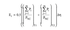
The amount of component i emitted (in kmol) is calculated from the following equation:
|
|
eq. (10.30) |
where:
● Pi is the partial pressure of component i (in Pa),
● PNC is the partial pressure of the non-condensable components
● T1 is the initial temperature of the system (in K) and
● T2 is the final temperature of the system (in K).
The moles of non-condensable components displaced, Δη, is calculated by the following equation:
|
|
eq. (10.31) |
where:
● R is the ideal gas constant (8,314.5 J/kmol-K), and
● V is the volume of the overhead space in the vessel (in m3).
Option 3
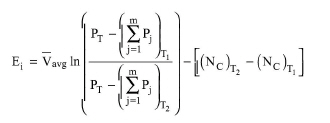
The amount of component i emitted (in kmol) is calculated from the following equation:
|
|
eq. (10.32) |
where:
● PT is the pressure of the vessel
● Pj is the partial pressure of component i (in Pa),
● NC are the total moles of the condensable components at temperature T,
● T1 is the initial temperature of the system (in K) and
● T2 is the final temperature of the system (in K).
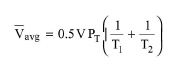
The average gas space molar volume during the heating process, Vavg
|
|
eq. (10.33) |
, is calculated by:
|
|
Heating emission are calculated up to the lightest emitted component’s boiling point, regardless of the final heating temperature, T2. |
This model accounts for emissions from reaction operations that involve generation and release of an inert gas. It is available in the following operations:
● Batch Stoichiometric Reaction,
● Batch Stoichiometric Fermentation,
● Perfusion Stoichiometric Fermentation,
● Continuous Stoichiometric Reaction,
● Continuous Kinetic Reaction,
● Continuous Equilibrium Reaction,
● Continuous Stoichiometric Fermentation,
● Continuous Kinetic Fermentation, and
It is assumed that the gas that leaves the system is saturated with VOC vapor(s) at the exit temperature. The mathematical model is identical to the Gas Sweep model (see Purging Emissions Model) with the gas produced playing the role of the sweeping gas.