The stoichiometric fermentation model can be used to simulate bio-transformations when the reaction kinetics are unknown or unimportant but the mass stoichiometry is known and the extent of reaction can be specified or calculated based on the concentration of a reference component. The extent of reaction is defined as the fractional conversion of the limiting component. It is possible to have simultaneous feeding of reactants during the reaction, if the Fed Batch options are selected/specified (see Fed Batch Tab).
● Batch Vessel Procedure in a Reactor
● Batch Vessel Procedure in a Seed Reactor
● Batch Vessel Procedure in a Bioreactor
● Batch Vessel Procedure in a Seed Bioreactor
● Batch Vessel Procedure in a Disposable Bioreactor
● Batch Vessel Procedure in a Disposable Seed Bioreactor
● Batch Vessel Procedure in a Fermentor
● Batch Vessel Procedure in a Seed Fermentor
● Inoculum Preparation Procedure in a Rocking Bioreactor
● Inoculum Preparation Procedure in a Roller Bottle
● Inoculum Preparation Procedure in a T-Flask
● Inoculum Preparation Procedure in a Shake Flask
● Inoculum Preparation Procedure in a Test Tube
The reactions are assumed to occur in a sequence (one after the other). In that sense, the calculations assume that the product mixture of the first reaction is the reacting mixture of the second, and so on. The reactants brought in by the feed stream (in the case that fed batch option is selected) are assumed to be initially present in the reactor as no kinetic considerations are made.
The user provides the mass or molar stoichiometric coefficients (Ai) of the various components for each reaction and the extent of reaction (x) based on either the limiting component or a reference component. Negative stoichiometric coefficients are used for reactants and positive for products. The coefficients can be supplied in either mass or molar units. The algorithm used by the program to perform the material balances for each reaction is explained in the following paragraphs.
If the extent of the reaction is expressed based on the limiting component then, first of all, the limiting component is identified. This is done based on the mass stoichiometry and the composition of the reacting mixture. If the extent of the reaction is expressed based on a user-defined component, then first of all, the program attempts to validate that the user-defined conversion is achievable (i.e., there are enough reactants for the reaction to proceed to such an extent). If that is not the case, then the conversion (x) is adjusted to reflect the maximum achievable conversion percentage (based on the extent-component chosen by the user).
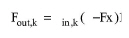
For the limiting component (k) or the extent-reference component (depending on what is the case) the following holds:
|
|
where:
● Fout,k is the mass flowrate of the component after the reaction,
● Fin,k is the mass flowrate of the component before the reaction, and
● x is the (possibly adjusted) reaction extent.
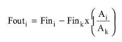
Now, the mass flowrate after the reaction (Fout,i) of any other component present (i) as a function of its mass flowrate (Fin,i) before the reaction, the extent of reaction (x), and the mass stoichiometric coefficients (Ai), is given by the following equation:
|
|
where Ak is the coefficient of the limiting or extent-reference component.
The same algorithm is repeated for all reactions specified using the product-mixture of reaction N-1 as the feed of reaction N.
When the aeration rate is set by the user (in Volume of air under standard conditions per Volume of fermentation broth per Minute - VVM), the flowrate of the aeration stream is adjusted by the fermentation model. If the aeration stream has a source unit procedure (e.g., a compressor), then the adjustment of its flowrate is recursively back - propagated till process feed streams are reached. At least one of the process feed streams that feed into the aeration stream must have non-zero flowrate. Only units with a single output stream can be part of the sequence of units that feed into an aeration stream. An exception to this rule is the ‘Custom Mixer’ which is not allowed to be part of the sequence even though it has a single output stream.
Vapor-liquid equilibrium calculations in the fermentor are not carried out. To account for gas components exiting in the gas outlet stream, the user must specify the removal fraction (Percent in Gas Outlet) for each component. The calculation of the gas outlet stream composition is based on materials that are available in the vessel after the completion of the fermentation.
You may also specify the extracellular percent (100% by default) of each of the reaction’s product components. This feature is useful when tracking of intracellular water is desired because it affects the performance of centrifugation, filtration, etc. further downstream. If the ‘Extra-Cell %’ of certain reaction product components is less than 100 (or in other words a fraction of the component is intracellular) and the ‘Primary Biomass’ and ‘Water’ components are identified (through the component registration dialog window), then the model automatically associates intracellular water with the intracellular reaction product components. Then, if a separator is used to remove intracellular components (i.e., removal of biomass by a centrifuge), the separation (removal %) of intracellular water will be the same as that of the intracellular component(s).
The average agitation power is estimated by multiplying the unit power requirement (kW/m3 of broth) by the liquid volume of the fermentor.
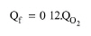
To estimate the overall heating or cooling requirement, the model considers the sensible heat of the inlet and outlet streams along with the heat of reaction. The calculation of the heat of reaction for aerobic systems is based on the oxygen uptake rate (Cooney et al., 1968):
|
|
eq. (A.52) |
where Qf is heat release in kcal/L-h and QO2 is the oxygen uptake rate in kmol/L-hr. A default value of -3750.0 kcal/(kg of oxygen utilized) is used based on the above model.
See Batch Vessel Operations: Equipment Sizing.
See Vacuum Pump Auxiliary Equipment Calculations.
1. Cooney, C. L., D. I. C.Wang, and R. I. Mateles (1968). Measurements of Heat Evolution and Correlation with Oxygen Consumption during Microbial Growth. Biotechnol. Bioeng. 11, 269-281.
The interface of this operation has the following tabs:
● Oper. Cond’s, see Fermentation Operations: Oper. Conds Tab
● Volumes, see Batch Vessel Operations: Volumes Tab
● Fed Batch, see Fed Batch Tab
● Reactions, see Stoichiometric Reaction/Fermentation Operation: Reactions Tab
● Vent/Emissions, see Reaction Operations: Vent/Emissions Tab
● Labor, etc, see Operations Dialog: Labor etc. Tab
● Description, see Operations Dialog: Description Tab
● Batch Sheet, see Operations Dialog: Batch Sheet Tab
● Scheduling, see Operations Dialog: Scheduling Tab