eq. (A.56)
This operation can be used to model any number of parallel or sequential reactions (material transformations) that take place continuously in a stirred tank reactor. It supports a wide variety of reaction kinetics. The inlet streams are assumed to be perfectly (and instantaneously) mixed with the material already in the reactor, so that the outlet stream composition is identical to that of the reactor contents.
● Continuous Kinetic Reaction Procedure in a CSTR
For a component A that enters this process step, the mass balance equation for a constant density system is given by the following equation:
|
|
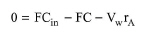
eq. (A.56) |
where F is the volumetric flowrate, Cin is the inlet concentration of component A, C is the outlet concentration of component A, and rA is the combined reaction rate of component A, given by eq. (A.43) - eq. (A.46). The above equations for each component constitute a set of non-linear equations which is solved numerically to calculate the outlet stream concentration.
For systems of variable reaction mixture density (which is often the case for gaseous reactions), the simplified overall material balance equation cannot be used. An excellent description of the formulation used in that case can be found in the literature (Fogler, 1992 - pp. 505-507).
To account for emissions, the user can specify the percentage of each component that is emitted. Please note that the specified percentage is based on the composition of the outlet stream (after the completion of the reaction).
If this unit operates in a batch plant, the feed flowrate F is calculated by dividing the volume of material that needs to be processed per cycle by the process time.
Three thermal modes of operation are available: Isothermal, Adiabatic, Set Heating or Cooling Duty. In the isothermal case, the program calculates the required heating or cooling duty. In the other two cases, it calculates the operating temperature.
The average agitation power is estimated by multiplying the agitation rate (kW/m3 of liquid mixture) by the total liquid volume of the step. It is assumed that all agitation power eventually dissipates into heat that contributes to the heating or cooling requirements of the step.
See Vessel Sizing (Continuous Operations).
See Vacuum Pump Auxiliary Equipment Calculations.
1. Fogler, H. S. 1992. Elements of Chemical Reaction Engineering, 2nd edition, Prentice Hall.
The interface of this operation has the following tabs:
● Oper. Cond’s, see Continuous Reaction Operations: Oper. Conds Tab
● Volumes, see Continuous Vessel Operations (Design Mode): Volumes Tab and Continuous Vessel Operations (Rating Mode): Volumes Tab
● Reactions, see Kinetic Reaction/Fermentation Operation: Reactions Tab
● Split, see Continuous Reaction / Storage Operations: Split Tab
● Vent/Emissions, see Reaction Operations: Vent/Emissions Tab
● Labor, etc, see Operations Dialog: Labor etc. Tab
● Description, see Operations Dialog: Description Tab
● Batch Sheet, see Operations Dialog: Batch Sheet Tab
● Scheduling, see Operations Dialog: Scheduling Tab