When setting up a parallel scheme, notice that all reactions should have at least one common component with another reaction. Otherwise, the parallel scheme will not me meaningful and a pop-up warning will be generated by the program.
This operation is used to represent any number of material transformations that take place in a stirred tank operating in batch mode and for which kinetic expressions are unknown or unimportant. It is possible to have simultaneous feeding of reactants during the reaction, if the Fed Batch options are selected/specified (see Fed Batch Tab).
● Batch Vessel Procedure in a Reactor
● Batch Vessel Procedure in a Seed Reactor
● Batch Vessel Procedure in a Bioreactor
● Batch Vessel Procedure in a Seed Bioreactor
● Batch Vessel Procedure in a Disposable Bioreactor
● Batch Vessel Procedure in a Disposable Seed Bioreactor
● Batch Vessel Procedure in a Fermentor
● Batch Vessel Procedure in a Seed Fermentor
● Batch Vessel Procedure in a Disposable Bioreactor
● Inoculum Preparation Procedure in a Rocking Bioreactor
● Inoculum Preparation Procedure in a Roller Bottle
● Inoculum Preparation Procedure in a T-Flask
● Inoculum Preparation Procedure in a Shake Flask
● Inoculum Preparation Procedure in a Test Tube
● Batch Storage in a Blending Tank Procedure
● Batch Storage in a Flat Bottom Tank Procedure
● Batch Storage in a Receiver Tank Procedure
● Batch Storage in a Horizontal Tank Procedure
● Batch Storage in a Vertical-on-Legs Tank Procedure
● Batch Storage in a Drum Procedure
● Batch Storage in a Disposable Generic Container Procedure
● Batch Storage in a Disposable Large Bag (on a Skid) Procedure
● Batch 1x1 Generic Box Procedure
● Batch 3x3 Generic Box Procedure
● Batch 5x5 Generic Box Procedure
● Batch 10x10 Generic Box Procedure
This operation uses the current vessel contents.
The reactions are assumed to occur in a sequence (one after the other) or in parallel according to the user specification. If the reactions are in sequence the calculations assume that the product mixture of the first reaction is the reacting mixture of the second, and so on. For reactions taking place in parallel, the specified reaction conversion is applied to the material amounts as they exist at the beginning of the parallel reaction scheme. A combination of reactions in sequence and in parallel can exist.
|
|
When setting up a parallel scheme, notice that all reactions should have at least one common component with another reaction. Otherwise, the parallel scheme will not me meaningful and a pop-up warning will be generated by the program. |
The user provides the mass or molar stoichiometric coefficients (Ai) of the various components for each reaction and the conversion of reaction (x) based on either the limiting component or a conversion reference component. Negative stoichiometric coefficients are used for reactants and positive for products. The coefficients can be supplied in either mass or molar units. The algorithm used by the program to perform the material balances for each reaction is explained in the following paragraphs.
If the conversion of the reaction is expressed based on the limiting component then, first of all, the limiting component is identified. This is done based on the mass stoichiometry and the composition of the reacting mixture. If the conversion of the reaction is expressed based on a reference component, then first of all, the program attempts to validate that the specified conversion is achievable (i.e., there are enough reactants for the reaction to proceed to such an extent). If that is not the case, then the conversion (x) is adjusted to reflect the maximum achievable conversion percentage for the chosen conversion reference component.
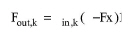
For the limiting component (k) or the conversion reference component (depending on what is the case) the following holds:
|
|
where:
● Fout,k s the mass flowrate of the component after the reaction,
● Fin,k is the mass flowrate of the component before the reaction, and
● x is the (possibly adjusted) reaction conversion of the selected component.
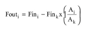
Now, the mass flowrate after the reaction (Fout,i) of any other component present (i), is given as a function of its mass flowrate (Fin,i) before the reaction, the conversion of reaction (x) based on the limiting or reference component, and the mass stoichiometric coefficients (Ai), by the following equation:
|
|
where Ak is the coefficient of the limiting or extent-reference component.
The same algorithm is repeated for all reactions specified using the product-mixture of reaction N-1 as the feed of reaction N.
You may also specify the percentage of each component (at the end of all reactions) that ends up in the gas exhaust stream through the Reaction Operations: Vent/Emissions Tab.
To estimate the overall heating or cooling requirements, the model considers:
● the enthalpy of each reacting mixture
● the temperature of each reaction
● the heat released or absorbed by each reaction as calculated based on the reaction extent and a user-defined enthalpy-reference component
The temperature of the last reaction determines the exit temperature of the process step which is displayed on the Operating Conditions tab. The heating and cooling requirements are summed up over all the reactions taking place, and the total is reported as the total heating (in kcal/h) and total cooling (in kcal/h) on the Oper. Conditions tab. Furthermore, based on your choices for heat transfer agents for each reaction, the demands for each agent are calculated and reported in the economic evaluation report; for more details, see , see Utilities Cost and Economic Evaluation Report (EER).
The average agitation power is estimated by multiplying the agitation rate (kW/m3 of liquid mixture) by the total liquid volume of the step. It is assumed that all agitation power eventually dissipates into heat that contributes to the heating or cooling requirements of the step.
See Batch Vessel Operations: Equipment Sizing.
See Vacuum Pump Auxiliary Equipment Calculations.
The interface of this operation has the following tabs:
● Oper. Cond’s, see Batch Reaction Operations: Oper. Conds Tab
● Volumes, see Batch Vessel Operations: Volumes Tab
● Fed Batch, see Fed Batch Tab
● Reactions, see Stoichiometric Reaction/Fermentation Operation: Reactions Tab
● Vent/Emissions, see Reaction Operations: Vent/Emissions Tab
● Labor, etc, see Operations Dialog: Labor etc. Tab
● Description, see Operations Dialog: Description Tab
● Batch Sheet, see Operations Dialog: Batch Sheet Tab
● Scheduling, see Operations Dialog: Scheduling Tab