This unit operation model can handle any number of biotransformation reactions and supports a wide variety of fermentation kinetics. A reaction can be initiated at a specific time relative to the beginning of the unit’s process time or when the concentration of a certain component exceeds or drops below a certain value. Similarly, a reaction can be terminated at a specific time relative to the end of the unit’s process time or when the concentration of a certain component exceeds or drops below a certain value. The contents of the vessel are assumed well mixed at any time point. It is possible to have simultaneous feeding of reactants during the reaction, if the Fed Batch options are selected/specified (see Fed Batch Tab).
● Batch Vessel Procedure in a Reactor
● Batch Vessel Procedure in a Seed Reactor
● Batch Vessel Procedure in a Bioreactor
● Batch Vessel Procedure in a Seed Bioreactor
● Batch Vessel Procedure in a Disposable Bioreactor
● Batch Vessel Procedure in a Disposable Seed Bioreactor
● Batch Vessel Procedure in a Fermentor
● Batch Vessel Procedure in a Seed Fermentor
● Batch Vessel Procedure in a Disposable Bioreactor
● Inoculum Preparation Procedure in a Rocking Bioreactor
● Inoculum Preparation Procedure in a Roller Bottle
● Inoculum Preparation Procedure in a T-Flask
● Inoculum Preparation Procedure in a Shake Flask
● Inoculum Preparation Procedure in a Test Tube
a) Batch Kinetic Fermentation: Modeling Calculations
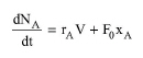
For a component A that reacts in a batch reactor, the generalized component balance is given by the following equation:
|
|
where V is volume of material in the reactor, NA is the amount (mass/moles) of component A, rA is the combined reaction rate of component A as a function of time, F0 is the (mass/ molar) flowrate of the feed stream (in the case of simultaneous feeding) and xA is the (mass /mole) fraction of component A in the feed stream. Note that if the amount of components is expressed in terms of mass, then F0 is a mass flow rate and xA is the mass fraction of component A. If the amount is in moles then F0 is a molar flow rate and xA is the mole fraction.
The (mass / molar) concentration of a component A is given by:
|
|
In the case of no feed stream (fed batch options are not selected) and constant density system the component balance reduces to:
|
|
The reaction rate rA of component A is given by:
|
|
where rAj is the reaction rate of component A due to reaction j and q is the overall number of reactions. If K is the rate reference component of reaction j, then, the reaction rate of component A due to reaction j is given by the following equation:
|
|
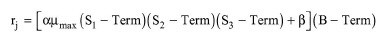
where νAj and νkj are the stoichiometric coefficients of components A and K in reaction j and can be specified on mass or molar basis. Negative stoichiometric coefficients are used for reactants and positive for products. The general rate expression (based on the rate reference component) of a reaction j is given by the following equation:
|
|
where α and β are constants and μmax is the maximum specific biomass growth rate. S1, S2 and S3 terms represent the kinetic expressions of three different components (e.g., substrates or reaction products) (S3 term can be used specifically for the inhibitor component). Finally, the B-Term represents the kinetic expression of the biomass component. The kinetic expression options for S1, S2 and S3 terms include Monod, Haldane (with product inhibition), Inhibition, first order, and none.
The above equations written for each component reacting in a batch fermentor constitute a system of ordinary differential equations, which are integrated numerically to calculate the final composition of the reacting mixture. The integration time is equal to the process time of the unit. A reaction, however, can be initiated or terminated at any time during that time period using the ‘Start’ and ‘End’ reaction criteria.
To account for emissions, the user can specify the percentage of each component that is emitted. Please note that the specified percentage is based on the composition of the mixture at the end of the reaction.
energy balances are performed that take into account the heat of reaction and the agitation power (it is assumed that all agitation power dissipates into heat). The model can estimate and record heating or cooling requirement as a function of time (see ‘Profiles’ paragraph further down).
The average agitation power is estimated by multiplying the unit power requirement (kW/m3 of liquid mixture) by the liquid volume.
The batch fermentation model can generate profiles of component concentration and heating/cooling duty as a function of time; for more details, see Kinetic Reaction Operations: Profiles Tab.
See Batch Vessel Operations: Equipment Sizing.
See Vacuum Pump Auxiliary Equipment Calculations.
1. Fogler, H. S. 1992. Elements of Chemical Reaction Engineering, 2nd edition, Prentice Hall.
The interface of this operation has the following tabs:
● Oper. Cond’s, see Fermentation Operations: Oper. Conds Tab
● Volumes, see Batch Vessel Operations: Volumes Tab
● Fed Batch, see Fed Batch Tab
● Reactions, see Kinetic Reaction/Fermentation Operation: Reactions Tab
● Vent/Emissions, see Reaction Operations: Vent/Emissions Tab
● Profiles, see Kinetic Reaction Operations: Profiles Tab
● Labor, etc, see Operations Dialog: Labor etc. Tab
● Description, see Operations Dialog: Description Tab
● Batch Sheet, see Operations Dialog: Batch Sheet Tab
● Scheduling, see Operations Dialog: Scheduling Tab