This operation can be used to model any number of parallel or sequential reactions (material transformations) that take place in a batch, stirred tank reactor. It supports a wide variety of reaction kinetics. A reaction can be initiated at a specific time relative to the beginning of the step’s process time or when the concentration of a certain component exceeds or drops below a certain value. Similarly, a reaction can be terminated at a specific time relative to the end of the step’s process time or when the concentration of a certain component exceeds or drops below a certain value. The contents of the reaction mixture are assumed well mixed at any time point. It is possible to have simultaneous feeding of reactants during the reaction, if the Fed Batch options are selected/ specified (see Fed Batch Tab).
● Batch Vessel Procedure in a Reactor
● Batch Vessel Procedure in a Seed Reactor
● Batch Vessel Procedure in a Bioreactor
● Batch Vessel Procedure in a Seed Bioreactor
● Batch Vessel Procedure in a Disposable Bioreactor
● Batch Vessel Procedure in a Disposable Seed Bioreactor
● Batch Vessel Procedure in a Fermentor
● Batch Vessel Procedure in a Seed Fermentor
● Batch Vessel Procedure in a Disposable Bioreactor
● Inoculum Preparation Procedure in a Rocking Bioreactor
● Inoculum Preparation Procedure in a Roller Bottle
● Inoculum Preparation Procedure in a T-Flask
● Inoculum Preparation Procedure in a Shake Flask
● Inoculum Preparation Procedure in a Test Tube
● Batch 1x1 Generic Box Procedure
● Batch 3x3 Generic Box Procedure
● Batch 5x5 Generic Box Procedure
● Batch 10x10 Generic Box Procedure
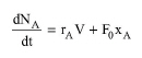
For a component A that reacts in a batch reactor, the generalized component balance is given by the following equation:
|
|
where V is volume of material in the reactor, NA is the amount (mass/moles) of component A, rA is the combined reaction rate of component A as a function of time, F0 is the (mass/ molar) flowrate of the feed stream (in the case of simultaneous feeding) and xA is the (mass /mole) fraction of component A in the feed stream. (If the amount of components is expressed in terms of mass, then F0 is a mass flow rate and xA is the mass fraction of component A and if the amount is in moles then F0 is a molar flow rate and xA is the mole fraction.)
The (mass / molar) concentration of a component A is given by:
|
|
In the case of no feed stream (fed batch options are not selected) and constant density system the component balance reduces to:
|
|
The component A reaction rate rA is given by:
|
|
where rAj is the reaction rate of component A due to reaction j and q is the total number of reactions. If k is the rate reference component of reaction j, then, the reaction rate of component A due to reaction j is given by the following equation:
|
|
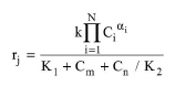
where νAj and νkj are the stoichiometric coefficients of components A and K in reaction j and can be specified on mass or molar basis. Negative stoichiometric coefficients are used for reactants and positive for products. The general rate expression (based on the rate reference component) of a reaction j is given by the following equation:
|
|
where Ci (kmol/m3) is the concentration of component i (kmol/m3), αi is the order of the j-th reaction with respect to component i, K1 and K2 are user-specified constants, Cm (kmol/m3) and Cn (kmol/m3) are the concentrations of components m and n that are identified by the user, and N is the total number of reactions.
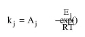
The reaction rate constant k is either specified by the user or calculated using an Arrhenius expression:
|
|
where Aj is the pre-exponential factor (or frequency factor), and Ej is the activation energy of the j-th reaction. Please be careful when you select the units and specify the values of kj or Aj. The units of the overall rate expression must be in kmol/m3-s.
The above equations written for each component reacting in a batch reactor constitute a system of ordinary differential equations that are integrated numerically to calculate the final composition of the reacting mixture. The integration time is equal to the process time of the unit. A reaction, however, can be initiated or terminated at any time during that time period using the ‘Start’ and ‘End’ reaction criteria.
For systems of variable reaction mixture density (which is often the case for gaseous reactions), the simplified overall material balance equation cannot be used. An excellent description of the formulation used in that case can be found in the literature (Fogler, 1992 - pp. 505-510).
The model performs VOC emission calculations for any of the following cases: 1) The reaction takes place under gas sweep conditions; 2) A gaseous component is released during the reaction that results in VOC emissions; and 3) The reaction takes place under vacuum and the leakage of air results in emissions.
A batch reactor can operate isothermally (at a constant operating temperature), adiabatically (no exchange of heat with the surroundings), or with an evenly distributed heating or cooling duty during the process time. Under isothermal conditions, the model calculates the heating or cooling requirement as a function of time. Read the ‘Profiles’ paragraph for information on how to view and plot the heating and cooling requirement as a function of time. The heating/cooling duty displayed on the first dialog window in kcal/h represents averaged values over the process time of the unit. Under conditions of specified heating or cooling duty of constant rate, the model calculates the temperature of the reacting mixture as a function of time (see Kinetic Reaction Operations: Profiles Tab below for information on how to view or plot the temperature profiles). Adiabatic operation is a special case of specified heating or cooling duty.
The average agitation power is estimated by multiplying the agitation rate (kW/m3 of liquid mixture) by the total liquid volume of the step. It is assumed that all agitation power eventually dissipates into heat that contributes to the heating or cooling requirements of the operation.
See Batch Vessel Operations: Equipment Sizing.
See Vacuum Pump Auxiliary Equipment Calculations.
1. Fogler, H. S. 1992. Elements of Chemical Reaction Engineering, 2nd edition, Prentice Hall.
The interface of this operation has the following tabs:
● Oper. Cond’s, see Batch Reaction Operations: Oper. Conds Tab
● Volumes, see Batch Vessel Operations: Volumes Tab
● Fed Batch, see Fed Batch Tab
● Reactions, see Kinetic Reaction/Fermentation Operation: Reactions Tab
● Vent/Emissions, see Reaction Operations: Vent/Emissions Tab
● Profiles, see Kinetic Reaction Operations: Profiles Tab
● Labor, etc, see Operations Dialog: Labor etc. Tab
● Description, see Operations Dialog: Description Tab
● Batch Sheet, see Operations Dialog: Batch Sheet Tab
● Scheduling, see Operations Dialog: Scheduling Tab