eq. (A.2)
Use this operation to simulate a cooling process that takes place in a vessel.
● Batch Vessel Procedure in a Reactor
● Batch Vessel Procedure in a Seed Reactor
● Batch Vessel Procedure in a Bioreactor
● Batch Vessel Procedure in a Seed Bioreactor
● Batch Vessel Procedure in a Disposable Bioreactor
● Batch Vessel Procedure in a Disposable Seed Bioreactor
● Batch Vessel Procedure in a Fermentor
● Batch Vessel Procedure in a Seed Fermentor
● Batch Vessel Procedure in a Disposable Bioreactor
● Inoculum Preparation Procedure in a Rocking Bioreactor
● Inoculum Preparation Procedure in a Roller Bottle
● Inoculum Preparation Procedure in a T-Flask
● Inoculum Preparation Procedure in a Shake Flask
● Inoculum Preparation Procedure in a Test Tube
● Nutsche Filtration Procedure
● Batch Distillation Procedure
● Batch Storage in a Blending Tank Procedure
● Batch Storage in a Flat Bottom Tank Procedure
● Batch Storage in a Receiver Tank Procedure
● Batch Storage in a Horizontal Tank Procedure
● Batch Storage in a Vertical-on-Legs Tank Procedure
● Batch Storage in a Drum Procedure
● Batch Storage in a Drum Procedure
● Batch Storage in a Tote Procedure
● Batch Storage in a Disposable Generic Container Procedure
● Batch Storage in a Disposable Large Bag (on a Skid) Procedure
● Batch 1x1 Generic Box Procedure
● Batch 3x3 Generic Box Procedure
● Batch 5x5 Generic Box Procedure
● Batch 10x10 Generic Box Procedure
The operation uses material as found in the host vessel at the end of the previous operation (if any). The results of the operation are left as the equipment contents at the end of the operation.
Several cooling options are available in this model. The cooling time can either be set or calculated. When calculated it can be based on a constant cooling or exponential type where the overall heat transfer coefficient is specified
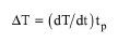
In the case of a constant cooling rate (dT/dt), the following equation is used to calculate either the cooling rate or the process time:
|
|
eq. (A.2) |
where ΔT = T0 - T1 is the temperature difference between the initial and the final states. When the user specifies the constant cooling rate, the above equation is solved for cooling time and vice versa.
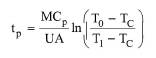
If an exponential cooling rate is selected, then the user sets the overall UA (kcal/h-°C) and the process time is calculated by the following equation:
|
|
eq. (A.3) |
where TC is the inlet temperature of the cooling agent, T0, T1 are the initial and final temperatures of the vessel contents and MCp is a collective term representing the sum of the vessel contents and equipment heat capacity (kcal/°C).
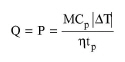
For all cooling options, and if the cooling agent is not ignored, the average cooling duty (Q) or power (P) is calculated using the following equation:
|
|
eq. (A.4) |
where η is either the cooling efficiency if a cooling agent is selected or the coefficient of performance (COP) if electring cooling is selected. The COP is defined as the ratio of cooling load (negative enthalpy change of material contents) to electricity consumption. Note that the COP corresponding to 1 “ton” of refrigeration (12,000 Btu/h) per unit of horse power is approximately 4.7.
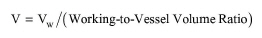
In Design Mode of calculation, the user specifies the max. allowable working to vessel volume ratio for this equipment. Also the program sets the working (liquid) volume (Vw) equal to the volume of material that is processed per cycle. The number of cycles per batch is specified through the Procedure Data Dialog: Scheduling Tab (Batch Process). The vessel volume (V) is then calculated using the following equation:
|
|
If the calculated vessel volume exceeds its maximum possible value (specified through the Equipment tab of the corresponding equipment’s interface), the program assumes multiple (identical) units operating in parallel with a total vessel volume equal to the calculated.
In Rating Mode, the user specifies the vessel volume and the number of units. The program calculates the working to vessel volume ratio and warns the user if its value is outside of its minimum and maximum limits.
See Vacuum Pump Auxiliary Equipment Calculations.
The interface of this operation has the following tabs:
● Oper. Cond’s, see Batch Cooling: Oper. Conds Tab
● Volumes, see Batch Vessel Operations: Volumes Tab
● Vent/Emissions, see Vessel Operations: Vent/Emissions Tab
● Labor, etc, see Operations Dialog: Labor etc. Tab
● Description, see Operations Dialog: Description Tab
● Batch Sheet, see Operations Dialog: Batch Sheet Tab
● Scheduling, see Operations Dialog: Scheduling Tab