SuperPro Designer performs venting and volatile organic compound (VOC) emission calculations for several batch operations that are common in the pharmaceutical and specialty chemical industries. Furthermore, venting is available for several continuous operation including reactions, storage, etc. Operations that have the option to perform vent/emissions calculations are those that can cause a change in the vapor phase while executed in equipment that accumulates material. Typical examples are Charge, Transfer In and Pull In operations executed in the context of Batch Vessel Procedures that cause the displacement of freeboard gases. If venting occurs then emission calculations are also possible to account for VOC gases that are swept away by the freeboard gases.
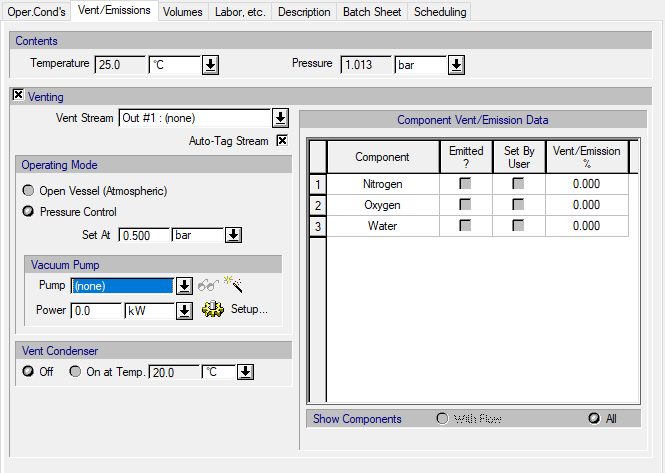
Operations that can perform vent/emissions will include a ‘Vent/Emissions’ tab in their dialog like the one shown in The ‘Vent/Emissions’ tab of the Charge operation. for the Charge operation. Venting is optional and, by default, assumed to be off except for certain operations including Purging / Inerting, Evacuation, Batch Stoichiometric Fermentation with aeration etc., that absolutely require the removal of gases. A closed vent corresponds to a closed-valve operation that does not allow any gases to escape, making pressure built-up possible. Note that, when not explicitly set by the user, the operating pressure is calculated by SuperPro Designer based on the amount of freeboard gases and the available equipment headspace.
If venting is turned on, the user can select the port through which gases will escape. By default, this port is the equipment’s ‘vent/emissions’ port (usually the top output port when available) but any other output port could be selected, provided that no other operation in the procedure uses it for purposes other than venting. Sharing of the same port among different operations for venting is possible. The streams connected to these vent/emission ports are by default classified as ‘emission’ streams (i.e., the ‘Auto-Tag Stream’ option is checked by default in the ‘Vent/Emissions’ tab of an operation).Vent streams are always assumed to be 100% vapor and their physical state options are locked (i.e., cannot be changed by the user).
The program allows for the selection of a venting policy namely:
● open vessel (atmospheric) operation or,
● pressurized vessel operation with a user-specified relief valve setting
In the case of the open vessel, the pressure inside the equipment during the corresponding operation is assumed to be equal to the ambient pressure even if an amount of air needs to introduced into the equipment to equalize the pressure. This is a common scenario in operations where the temperature of the equipment contents decreases (e.g., Batch Cooling) or material is removed (e.g., Transfer Out). In the pressurized vessel case, gases can only escape if the pressure exceeds the relief-valve setting but air cannot flow into the equipment. In other words, the pressure of the equipment contents can be lower or equal to the relief valve setting.
The ‘Vent/Emissions’ tab of the Charge operation.
SuperPro Designer offers the option of using a vent condenser with a user-set temperature. By default, for new operations the vent condenser is off. To turn the vent condenser on, the user must check the respective radio button and specify an appropriate temperature. In general, the use of a vent condenser will result in a decreased concentration of VOCs in the vent stream.
The user must select which components are to be considered as emitted and perhaps specify the emitted/vented percentage (%) for some of them. The Vent/Emission% expresses the portion of a component that is vented (e.g., sent to the vent/emissions line from the vessel contents.)
|
|
Components that are 100% in the vapor phase (based on the operation’s PS toolbox) will be automatically checked by SuperPro as emitted. |
|
|
Components that are 100% in the liquid phase (based on the operation’s PS toolbox), may or may not be checked as ‘emitted/vented’. If they are checked as ‘emitted/vented’, then: |
As a general rule, please use the following guidelines when including checking a component as ‘Emitted’ in the Vent/Emissions tab of an operation:
In order to include a component in the set of ‘emitted’ components on the Vent/Emissions tab, it is best to make sure that this component has valid vapor pressure estimation parameters. If that is not possible, then the user must provide their own ‘vent/emission percentage’ (thus, click on the “Set-by-User” option) and in order to avoid pressure calculation issues, the user should make sure that the component is perceived as 100% liquid by the operation’s PS toolbox.
In the Vent/Emissions tab of reaction and fermentation operations there is also the option to sweep the contents with a sweep gas at a specified volumetric rate (see The ‘Vent/Emissions’ tab of the Batch Stoichiometric Fermentation operation.).
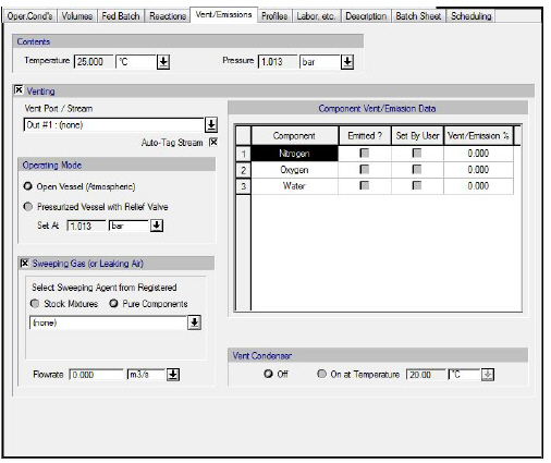
The ‘Vent/Emissions’ tab of the Batch Stoichiometric Fermentation operation.
|
|
If the Gas Sweep option is on, the entire amount of sweeping gas is mixed to the equipment contents before the Vent/Emission calculations are performed. |
The calculation of vent/emissions by SuperPro is based on the pressure conservation principle: headspace gases are removed from the equipment contents in order to satisfy the user-defined pressure setting.
|
|
There is a substantial difference between SuperPro emission calculations and EPA emission calculations. SuperPro emission calculations are pressure-driven in the sense that the amount emitted is determined by the program in order to maintain pressure to the desired value. On the other hand, EPA emission calculations are volume-driven in the sense that the amount (volume) of emissions is pre-determined (e.g., by the amount of displaced gas or sweep gas). As a result, EPA emission calculations result in pressure inconsistencies. |
The gases are removed from the equipment’s headspace, according to the methodology described below:
1. After the solution of the operation’s mass and energy balances, the program determines the physical state of the equipment contents at their respective temperature and pressure based on a Rigorous VLE model. If the operation uses the Shortcut PS toolbox then the physical state is going to be determined by the Raoult’s law model. Otherwise, the same VLE model used by the operation will be employed. This principle is called the Raoult’s law-or-better rule. Subsequently, the composition of the vent stream is assumed to be equal to the composition of the gas phase inside the equipment.
2. For operations like Batch Heating, Evacuation or Venting where there is an implied gradual change in temperature or pressure, an average vent stream concentration is determined by advancing from the initial to the final condition in 5 homogeneous steps. Clearly, the average vent stream composition will be different from the composition of the gas phase of the vessel contents at the end of the operation.
3. If the vent condenser is on at a set temperature Tc, then the vent stream is re-flashed at the corresponding temperature (Tc) so that a new composition for the vent draw is acquired.
4. Given the composition of the vent draw stream, the program will calculate the amount that must be vented so that the pressure of the remaining gases inside the equipment headspace matches the desired value. Notice that in case 3 above (where the composition of the vent draw is different than the composition of the gas phase in the vessel), this is not a direct calculation but requires an iterative procedure (e.g., a Newton-Raphson) which could fail if one or more components in large amounts change phase significantly from the temperature of the vessel to the operating temperature of the condenser (Tc)..
|
|
In general, when an operation uses the shortcut toolbox, the actual pressure of the equipment contents after venting will be slightly different than the displayed value because the physical state of the equipment contents as calculated by the shortcut toolbox will be different from the respective physical state as calculated by Raoult’s Law. |
In continuous operations where the vent is open, the entire amount of the gas phase after the solution of mass and energy balances (as inferred by the Raoult’s law-or-better rule) will be directed to the vent stream. Otherwise (i.e, in case the vent is closed), both the liquid and the gas portion of the contents will exit from the same stream. See Vent/Emission Calculations In Batch and Continuous Operations.
If an operation needs to vent gas, and the operating pressure is less than the ambient pressure, then that operation needs to use a vacuum pump in order to pump out that gas. In that case, SuperPro displays a set of vacuum pump specification controls to account for the capital cost, operating cost and scheduling challenges associated with that vacuum pump. These controls are either shown in the “Vent/Emissions” tab (if one exists) or in the “Oper. Cond’s” tab. More specifically:
● For operations that do their own venting calculations, and so they don’t have a “Vent/Emissions” tab (e.g., drying operations), these controls are displayed in the “Oper. Cond’s” tab.
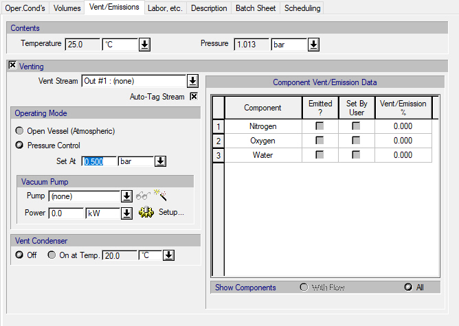
● For operations that use a “Vent/Emissions” tab (e.g., vessel operations), these controls are displayed in the “Vent/Emissions” tab, as long as “Venting” is checked and the pressure control setting is less than the ambient pressure (see The ‘Vent/Emissions’ tab of the Continuous Storage operation when the pressure control (relief valve) setting is lower than the ambient pressure setting. and Vessel Operations: Vent/Emissions Tab)..
●
The ‘Vent/Emissions’ tab of the Continuous Storage operation when the pressure control (relief valve) setting is lower than the ambient pressure setting.
Note that the ambient pressure can be specified through the Reference Conditions dialog. To display this dialog, right-click on white space in the flowsheet, and then click Reference Conditions from the context menu that comes up. By default, the ambient pressure is set to 1 atm.
Initially, no vacuum pump is selected and the vacuum pump’s power consumption is set to zero. If you want to include equipment sizing, costing and scheduling calculations in the simulation, click on the vacuum pump list box to bring up a list of available vacuum pumps in order to select one. If you just want to account for the power consumption of the vacuum pump, and skip equipment sizing, costing and scheduling calculations, then you may select “(none)” (default) in the vacuum pump selection list box.
To create a new vacuum pump and add it to the list of available vacuum pumps, click on the New button ( ). This will open the Auxiliary Equipment Properties dialog for auxiliary equipment of the vacuum pump type. Through this dialog, you can view or edit the properties of the vacuum pump auxiliary equipment resource, such as the name, sizing option (design mode vs rating mode), number of units, size (power), vacuum pump type (liquid ring, roots, or other), purchase cost, consumables, scheduling, etc. The same dialog is displayed when you select one of the available vacuum pumps from the list and click on the View/Edit Properties button (
 ). For more information on this dialog, see Vacuum Pumps and Auxiliary Equipment Properties Dialog: Aux. Equipment tab (Vacuum Pump).
To view or change the vacuum pump power specification options, click on the Setup button. This will bring up the Vacuum Pump Power Consumption Dialog (see The Vacuum Pump Consumption dialog.).
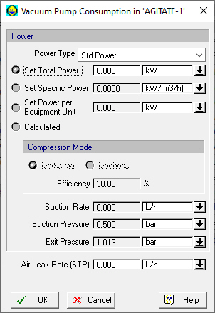
The Vacuum Pump Consumption dialog.
Through this dialog, the user may choose among the following options for specifying the power consumption of the vacuum pump:
● Set Total Power (default)
● Set Specific Power
● Set Power per Equipment Unit
● Calculated
In addition, the user may specify the volumetric flowrate of the air leak rate at the program’s standard temperature and pressure (STP) conditions. This value is used to calculate the power consumption of the vacuum pump when the “Calculated” option is selected. It is also used in vent/emissions calculations.
If the “Set Total Power” option is selected, then the user may specify the total power (i.e., over all units), either through this dialog, or through the operation’s “Vent/Emissions” or “Oper. Cond’s” tab.
If the “Set Specific Power” option is selected, then the user must specify the specific power, which is defined as the (total) power divided by the (total) suction rate (the volumetric flow rate of gas at vacuum pump inlet).
If the “Set Power per Equipment Unit” option is selected, then the user must specify the power per equipment unit, which is defined as the total power divided by the number of vacuum pump (auxiliary) equipment units.
If the “Calculated” option is selected, then the power consumption of the vacuum pump (auxiliary) equipment resource will be calculated by the program depending on the selected (isothermal or isochoric) compression model. If no vacuum pump is selected in the operation’s “Vent/Emissions” or “Oper. Cond’s” tab, or the vacuum pump type of the selected vacuum pump is set to “Other”, then both options will be available. If the vacuum pump type of the selected vacuum pump is set to “Liquid Ring”, then only the isothermal compression model option will be available, and if the vacuum pump type of the selected vacuum pump is set to “Roots”, then only the isochoric compression model option will be available.
For the isothermal compression model option (which is suitable for liquid ring vacuum pumps), the isothermal compression power can be estimated as:
Isothermal Compression Power = Suction Rate * Suction Pressure * ln(Exit Pressure/Suction Pressure).
The suction rate is defined as the volumetric flow rate of gas at vacuum pump inlet. It is calculated as the sum of the volumetric flow rate of the evacuated gas and the volumetric flow rate of air leak into the system. The specified air leak rate at the program’s standard temperature and pressure (STP) conditions (QS) is converted into volumetric flow rate (Q) based on the ideal gas law: Qair = Qair,STP (PstdT)/(P Tstd), where Pstd is the standard pressure (1 bar by default), Tstd is the standard temperature (0oC by default), P is the suction pressure, and T is the suction temperature. The suction pressure and temperature are defined as the pressure and temperature, respectively, at vacuum pump inlet. The suction pressure is assumed equal to the operating pressure, and the suction temperature is assumed equal to the temperature of the evacuated gas.
By default, the exit pressure is assumed equal to the ambient pressure.
For the isochoric compression model option (which is suitable for roots vacuum pumps), the isochoric compression power can be estimated as:
Isochoric Compression Power = Suction Rate * (Exit Pressure - Suction Pressure),
The actual power consumption of the vacuum pump equipment resource is then calculated as:
Power = Compression Power / Efficiency,
where the efficiency factor takes into consideration the mechanical energy losses in the pump (e.g., wall friction losses, turbulent exchange losses, thermodynamic losses). Usually, the efficiency is 0.25-0.4 for a liquid ring vacuum pump. A suitable efficiency for a roots vacuum pump is 83%. By default, the compression efficiency is assumed equal to 30% for an isothermal compression model and 83% for an isochoric compression model.


