This tab is part of the simulation data dialog of the following operations:
● Batch Stoichiometric Reaction,
● Batch Stoichiometric Fermentation,
● Perfusion Stoichiometric Fermentation,
● Continuous Stoichiometric Reaction,
● Continuous Kinetic Reaction,
● Continuous Equilibrium Reaction,
● Continuous Stoichiometric Fermentation,
● Continuous Kinetic Fermentation, and
You can access the simulation data dialog of an operation through the Operation Data item of the corresponding unit procedure’s context menu (right-click on the unit procedure icon to bring up its context menu).
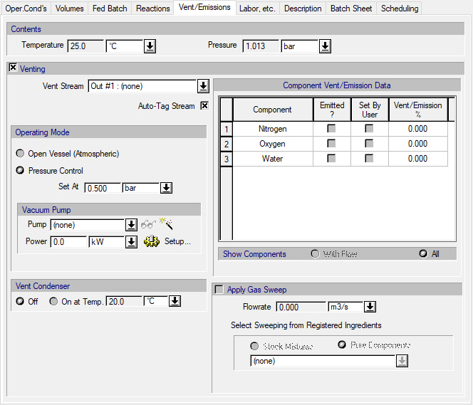
The following table shows a brief description of the variables appearing in this tab. The table also displays their default values and their generally acceptable range:
|
Variable |
Default Value |
Range |
|
|
||
|
● Temperature (oC) |
25.0 |
Positive |
|
● Pressure (bar) |
1.013 |
Positive |
|
● Venting |
Yes |
Yes/No |
|
○ Vent Port / Stream |
<none> |
Any Output Port |
|
○ Auto-Tag Stream |
Yes |
Yes/No |
|
● Pressure Control Set At (bar) |
1.013 |
Positive |
|
○ Vacuum Pump |
<none> |
Any Vacuum Pump |
|
○ Vacuum Pump Power (kW) |
0.0 |
Positive |
|
○ Emitted ? |
No |
Yes/No |
|
○ Set by User |
No |
Yes/No |
|
◙ Vent/Emission (%) |
0.0 |
0-100 |
|
○ Vent Condenser Temperature (oC) |
20.0 |
Positive |
|
○ Apply Gas Sweep? |
No |
Yes/No |
|
○ Sweeping Agent |
<none> |
Any Stock Mixture or Pure Component |
|
○ Flowrate of Sweeping Gas (m3/s) |
0.0 |
Positive |
Symbol Key: ○ User-specified value (always input); ● Calculated value (always output); ◙ Sometimes input, sometimes output
The following list describes the available specification choices in this tab; for more details on how these are implemented, see Vent/Emission Calculations In Batch and Continuous Operations.
•‘Venting’ Option...
If venting is off, freeboard gases are not allowed to escape (closed-valve operation), thereby contributing to a pressure increase.
If venting is turned on, freeboard gases are vented. The user can select between atmospheric or pressurized vessel operation with a relief valve setting specification.
•Venting Operating Mode...
‘Atmospheric’ operation is equivalent to having the release valve open so the pressure inside the vessel is equal to the atmospheric pressure. Operation under this setting allows for gases inside the vessel to escape from the vessel, but also, for atmospheric air to be introduced into the vessel in order to preserve the pressure. For more details on how SuperPro Designer calculates the amount that is vented from an operation, see Vent/Emission Calculations In Batch and Continuous Operations.
The ‘Pressurize Control’ mode allows pressure to build up inside an equipment, until the value of the pressure control / relief valve setting is reached. If more gases are accumulated so the pressure exceeds the pressure control setting, then a portion of it will be vented from the vessel so that the pressure matches the pressure control setting specified. Notice however that, if the pressure is lower than the pressure control setting, no air will be allowed into the vessel.
For continuous operations the venting operating mode is simply another way to specify the pressure of the operation. The pressure specification in this tab will update the respective specification of the Oper. Conds. tab (if applicable) and vice versa. Also notice that the specified pressure will be inherited by the operation’s output stream(s).
•Vacuum Pump Controls...
Note that the vacuum pump controls are only displayed if the ‘Venting’ option is checked and the operating mode is set to ‘Pressure Control’ and the pressure control setting is set at a lower pressure than the ambient pressure.
Click on the vacuum pump list box to bring up a list of available vacuum pumps in order to select one, or select “(none)” (default) if equipment sizing, costing and scheduling calculations are not important.
To create a new vacuum pump and add it to the list of available vacuum pumps, click on the New button ( ). This will open the Auxiliary Equipment Properties dialog for auxiliary equipment of the vacuum pump type (see Auxiliary Equipment Properties Dialog: Aux. Equipment tab (Vacuum Pump)). Through this dialog, you can view or edit the properties of the auxiliary equipment resource (e.g., name, size, purchase cost, consumables, scheduling).
The same dialog is displayed if you select one of the available vacuum pumps from the list and click on the View/Edit Properties button ( ).
).
Click on the Setup button to display the Vacuum Pump Consumption dialog (see Vacuum Pump Power Consumption Dialog), and select different options for specifying the power consumption of the vacuum pump. By default, the vacuum pump power specification option is “Set Total Power” and the total power consumption of the vacuum pump can be set by the user (the default value is zero). For more information, see Vacuum Pump Auxiliary Equipment Calculations.
In addition, through the Vacuum Pump Consumption dialog you can also specify a flowrate for leaking air if the operation takes place under vacuum.
•‘Emitted ?’ Component Option...
In order for component to included in the vent/emissions calculations the corresponding option must be checked. Components that are 100% in the gas phase will be automatically checked as being emitted.
•‘Set by User’ Component Option...
Check this box to set the emission percentage for particulate and other components for which the VOC emission models do not apply or the respective VLE-related component properties can not be specified.
For more information on how and when components are set as ‘Emitted?’, see Adding a Component to the Emitted/Vented List.
•Vent Condenser Options...
If the vent condenser is on then the vent stream will be re-flashed at the condenser’s temperature, resulting in a reduced amount of VOCs in the vent stream (see Vent/Emission Calculations In Batch and Continuous Operations).
•Apply Gas Sweep Option...
Specify the flowrate of a sweeping gas if the vessel is blanketed with an inert gas during the duration of the reaction.