eq. (10.1)
SuperPro Designer is equipped with dedicated models for calculating VOC emissions from wastewater treatment plants and cooling. There are five types of emission calculation models in the current version of the software:
1. The first type includes emissions from tanks and basins with quiescent surfaces (e.g., equalizers, neutralizers, clarifiers, thickeners, flotation, and oil separation units). The removal of VOC vapor(s) from tanks with quiescent surfaces occurs due to natural volatilization, i.e., mass transfer across open surfaces.
2. The second type includes emissions from aerated tanks equipped with surface or diffused aeration systems. The removal of VOC vapor(s) from such tanks occurs due to surface volatilization for mechanically aerated systems or due to stripping for tanks with diffused aeration systems.
3. The third type includes emissions from trickling filters. Trickling filters are modeled as packed-media systems, in which volatilization is the primary removal mechanism for all VOC gases. Note that this is a conservative assumption for compounds that are biodegradable.
4. The fourth type includes emission calculation models for junction boxes. Junction boxes combine wastewater streams flowing into a treatment plant. These boxes are usually open to the atmosphere and VOC emissions occur in a similar manner as emissions from quiescent surface tanks.
5. Finally, the fifth type includes emission calculation models for cooling towers. The inlet water stream in cooling towers may contain volatile contaminants whose removal occurs in a similar manner as emissions from aerated tanks.
The emission models for trickling filters, junction boxes and cooling towers are described as part of their operation models; for more details, see:
A description of the VOC emission models for quiescent and agitated tanks follows below.
This model is available in the following operations:
● Inclined Plate (IP) Clarification,
● Thickening,
● Flotation,
● Oil Separation, and
● Equalization.
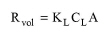
VOC emissions from tanks with quiescent surfaces (clarifiers, thickeners, equalizers, etc.) occur due to natural volatilization, i.e., mass transfer across open surfaces. To account for VOC emissions in such tanks, you may either select the emission calculation model or simply specify the emission percent for a VOC component. The model calculates the rate of mass transfer across the air-wastewater interface as follows:
|
|
eq. (10.1) |
where:
● Rvol is the rate of compound removal by volatilization (kg/s),
● KL is the overall mass transfer coefficient (m/s),
● CL is the VOC concentration in bulk liquid (kg/m3), and
● A is the surface area of the tank (m2).
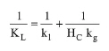
The value of CL is calculated based on an overall component mass balance. The overall mass transfer coefficient depends upon the resistances of the gas and liquid phases. It is calculated as:
|
|
eq. (10.2) |
where:
● kl is the mass transfer coefficient of the liquid phase (m/s),
● kg is the mass transfer coefficient of the gas phase (m/s), and
● Hc is the dimensionless Henry's law constant.
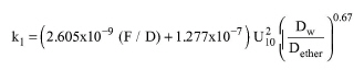
The value of Hc is retrieved from the pure components databank. Two different models have been implemented in order to calculate the mass transfer coefficients of the liquid phase. The first model, which is accepted by the US EPA, utilizes two correlations formulated by Springer et al. (1984). These are based upon the wind speed at ten meters (U10) above the liquid surface and the fetch-to-depth ratio (F/D) of the tank under consideration. ‘Fetch’ is the linear distance across the impoundment (EPA, 1994).
For F/D < 51.2 (originally developed for 14 < F/D < 51.2),
|
|
eq. (10.3) |
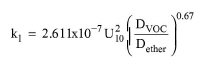
And, for F/D > 51.2,
|
|
eq. (10.4) |
where:
● DVOC is the diffusivity of the VOC component in water (m2/s), and
● Dether is the diffusivity of ether in water (m2/s).
The above equations were validated by Springer et al. for U10> 3.25 m/s and may lead to lower accuracy for U10< 3.25 m/s.
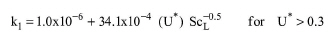
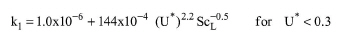
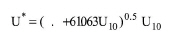
The second model estimates kl using the correlations developed by Mackay and Yeun (1983):
|
|
eq. (10.5) |
|
|
eq. (10.6) |
where:
|
|
eq. (10.7) |
|
|
eq. (10.8) |
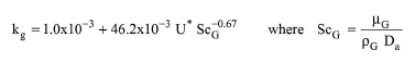
In both cases, the gas phase mass transfer coefficient is calculated using the equation developed by Mackay and Matasugu (Hwang, 1982):
|
|
eq. (10.9) |
where:
● μL is the viscosity of water (kg/m-s),
● μG is the viscosity of air (kg/m-s),
● ρL is the density of water (kg/cm3),
● ρG is the density of air (kg/cm3),
● Dw is the diffusivity of the VOC component in water (m2/s), and
● Da is the diffusivity of the VOC component in air (m2/s).
The above properties are retrieved from the components databank.
1. U. S. Environmental Protection Agency (EPA). 1994. “Air Emissions Models for Waste and Wastewater” Rep. EPA-453/R-94-080A. Research Triangle Park, NC: Office of Air Quality Planning and Standards.
2. Springer, C., P. D. Lunney, and K. T. Valsaraj. 1984. “Emission of Hazardous Chemicals from Surface and Near Surface Impoundments to Air,” Project Number 808161-02. Cincinnati, OH: U.S. Environmental Protection Agency (EPA), Solid and Hazardous Waste Research Division.
3. Mackay, D., and A. T. K. Yeun. 1983. “Mass Transfer Coefficient Correlations for Volatilization of Organic Solutes from Water,” Environmental Science and Technology. 17: 211-217.
4. Hwang, S. T. 1982. “Toxic Emissions from Land Disposal Facilities,” Environmental Progress. 1: 46-52.
This model is available in the following operations:
● Kinetic Well-Mixed (WM) Aerobic Bio-Oxidation,
● Stoichiometric Plug-Flow (PF) Aerobic Bio-Oxidation, and
● Kinetic Plug-Flow (PF) Aerobic Bio-Oxidation.
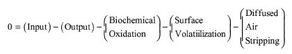
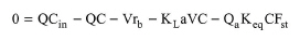
In agitated tanks, such as aeration basins, VOC emissions result from surface volatilization and diffused air stripping (if diffused air is used for aeration). The general material balance equation for a component that biodegrades and is emitted is given by the following equation:
|
|
eq. (10.10) |
Or
|
|
eq. (10.11) |
where:
● Q is the liquid flow rate,
● V is the reactor volume,
● Cin is the inlet concentration,
● C is the outlet concentration (which is the same as the concentration in the reactor),
● rb is the biodegradation rate,
● KLa is the overall mass transfer coefficient,
● Qa is the air flow rate (in case of diffused aeration),
● Keq is the equilibrium constant, and
● Fst is the saturation term (which represents the extent of saturation of the exiting gas stream).
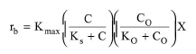
In general, the biodegradation rate is a function of substrate concentration, oxygen concentration, and biomass concentration. Various expressions are available for the effect of substrate. The overall equation with a Monod-type substrate expression is written as follows:
|
|
eq. (10.12) |
where:
● Kmax is the maximum rate constant,
● Ks is the half saturation constant for the substrate,
● C0 is the oxygen concentration,
● K0 is the half saturation constant for oxygen, and
● X is the biomass concentration.
Alternative expressions for the substrate and oxygen terms are also available. The components databank includes data for Kmax and Ks for a large number of chemical components; for more details, see Pure Component Properties.
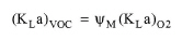
The overall mass transfer coefficient of a VOC component is estimated as a function of the oxygen mass transfer coefficient in wastewater, using a proportionality coefficient, ψM:
|
|
The value of (KLa)O2 in the wastewater is a user input to the program (parameter named ‘Oxygen Mass Transfer Coefficient at 20 oC’ on the Vent/Emissions tab).
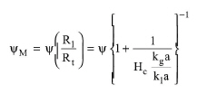
The value of ψM is calculated by the following equation (Hsieh et al., 1993):
|
|
where:
● y is a dimensionless proportionality constant,
● kla is the mass transfer coefficient of the liquid phase (1/s), and
● kga is the mass transfer coefficient of the gas phase (1/s).
The proportionality constant is calculated using the following equation (Corsi and Card, 1991):
|
|
where:
● DVOC is the diffusion coefficient of a VOC component in water (m2/s),
● DO2 is the diffusion coefficient of oxygen in water (m2/s)., and
● n is an exponent.
The exponent n varies from 0.5 for penetration and surface renewal theories to 1.0 for the two-film theory (Corsi and Card, 1991). Typically, it has a value between 0.5 and 0.6 (Mihelcic et al., 1993). SuperPro Designer uses a default value of 0.6 for all emitted component. A different value can be specified for each component. The diffusion coefficients of components are retrieved from the components databank of the program; for more details, see Pure Component Properties.
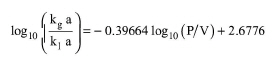
For mechanically aerated systems, the (kga/kla) ratio can be estimated using the following empirical equation (Hsieh et al., 1993):
|
|
eq. (10.16) |
where:
● P is the mechanical power consumed for surface aeration, and
● V is the liquid volume of the aeration basin.
The ratio (P/V) is calculated by the program as part of the simulation. Alternatively, you have the option to set the value of the (kga/kla) ratio or set the value of the (Rl/Rt) ratio. This specification option and the exponent n are specified for each component through the ‘Vent/Emissions’ tab, and more specifically, through a component’s ‘Emission Model’ dialog. To open this dialog, select a component by clicking on its row number and click the Emission model button which is available on this tab. By default, a (Rl/Rt) ratio equal to one is used for all emitted components.
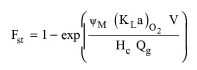
For diffused aerated systems, the Fst term is calculated by the following equation:
|
|
eq. (10.17) |
To calculate yM, you have the option to set either the value of the (kga/kla) ratio or the value of the (Rl/Rt) ratio. Again, these options are available through the ‘Vent/Emissions’ tab of the corresponding operation and they can be specified for each emitted component. The choice between surface air (mechanically aerated system) and diffused air (diffused aerated system) is specified through the ‘Oper. Cond’s’ tab of the corresponding operation.
The equilibrium constant is estimated by:
|
|
eq. (10.18) |
where R is the universal gas constant and T is temperature.
The above equations are written for each chemical component entering an aeration basin. These constitute a set of non-linear equations, which is solved numerically to calculate the exit concentration and the emission rate of each component.
1. Hsieh, C.-C., K. S. Ro, and M. K. Stenstrom, “Estimating Emissions of 20 VOCs. I: Surface Aeration, II: Diffused Aeration”, J. of Env. Engr., Vol. 119, No. 6, Nov./Dec. 1993, ASCE, ISSN 0733-9372.
2. Corsi, R. L., and T. R. Card. 1991. “Estimation of VOC Emissions Using the BASTE Model,” Environmental Progress. 10: 290-299.
3. Mihelcic, J. R., C. R. Baillod, J. C. Crittenden, and T. N. Rogers. 1993. “Estimation of VOC Emissions from Wastewater Facilities by Volatilization and Stripping,” Journal of Air and Waste Management Association. 43: 97-105.
4. Melcer, H, J. P. Bell, D. J. Thomas, C. M. Yendt, J. Kemp, and P. Steel. 1994. “Modeling Volatile Organic Contaminants' Fate in Wastewater Treatment Plants,” Journal of Environmental Engineering. 120: 588-609.
5. Melcer, H. 1994. “Monitoring and Modeling VOCs in Wastewater Facilities,” Environmental Science and Technology. 28: 328A-335A.
6. Tchobanoglous G. and F.L. Burton (1991). “Wastewater Engineering: Treatment, Disposal, and Reuse”, Third edition, Metcalf & Eddy, Inc., McGraw-Hill, Sec. 10-1.
7. Wong-Chong, G.M., and R.C. Loeht: Water Res., vol. 9, p. 1099, 1975.