eq. (A.77)
A trickling filter is a packed bed of media covered with slime growth over which wastewater is passed. As the waste passes through the filter, organic matter present in the waste is removed by the biological film (Eckenfelder, 1989).
Plastic packings are employed in depths up to 12.2 m (40 ft), with hydraulic loadings as high as 0.16 m3/m2-min (4.0 gal/ft2-min). Depending on the hydraulic loading and depth of the filter, BOD removal efficiencies as high as 90% have been attained on some wastewaters.
● Trickling Filtration Procedure
In terms of material balances, the trickling filter is modeled as a stoichiometric reactor. The user provides the stoichiometry and the extent of reaction (based on a limiting or reference component) for any number of biochemical oxidation and other type of reactions.
In Design Mode of calculation, one of two models can be utilized to size the trickling filter:
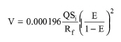
The National Research Council (NRC) model is based on the data analysis of stone media trickling filter plants. It considers that the contact between the filter media and organics depends on the filter dimensions. The filter volume V is given by the following equation:
|
|
eq. (A.77) |
where:
● E is the fraction of BOD5 removed
● Q is the influent flowrate (m3/day)
● Si is the influent BOD5 (mg/l)
● Rf is the recycle factor
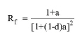
The recycle factor is defined as:
|
|
eq. (A.78) |
where:
● d is the weighing factor value (typical value = 0.9)
● a is the recycle ratio (recirculation flow / influent flow)
The above equation is used to calculate the required volume, V, of the trickling filter. The specified hydraulic loading (in m3/m2-day) along with the recycle ratio are used to calculate the required cross sectional area, A. Then, the depth of the filter is calculated by dividing the volume by the area.
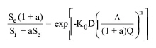
The Eckenfelder Model assumes that the trickling filter can be represented as a plug flow reactor and the substrate utilization follows first order kinetics:
|
|
eq. (A.79) |
where:
● Se is the effluent BOD5 (mg/l)
● Si is the influent BOD5 (mg/l)
● D is the depth of filter media (m)
● A is the cross sectional area of filter (sq.m)
● n a model-constant
● K0 is the treatability factor (1/day)
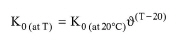
The constant, n, and the treatability factor, K0, are functions of the packing media. The program provides values for six different media types (the values of K0 are for 20 °C). The temperature correction factor (J = 1.035) is used to correct the treatability factor for temperatures different from 20 °C using the following equation.
|
|
eq. (A.80) |
The Eckenfelder equation is solved for D, to calculate the required depth of the filter. The cross sectional area, A, is calculated based on the hydraulic loading rate and the recycle ratio. Then, the filter volume is calculated by multiplying the cross sectional area by the depth of the filter.
If the calculated cross sectional area is greater than the area that corresponds to the maximum diameter, then the model assumes multiple filters operating in parallel.
Emissions of VOCs from trickling filters occur due to stripping caused by natural or forced air ventilation. The trickling filter is modeled as a packed-media (Corsi and Card, 1991). The emission calculations follow (they are done after) the biodegradation material balances.
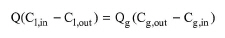
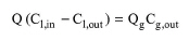
The mass balance for a particular VOC around a trickling filter operating countercurrently is written as follows:
|
|
eq. (A.81) |
where Q is the wastewater flowrate in (m3/s) and Qgis either the natural or forced air ventilation rate, or aeration rate, in (m3/s). Ci,inand Ci,outare the influent and effluent concentrations of the VOC in the wastewater in (g/m3), respectively. Cg,in and Cg,out are the initial and final concentrations of the VOC in the air in (g/m3), respectively. Since the initial concentration of the VOC in the circulating air is zero, Cg,in is zero, and the above equation becomes:
|
|
eq. (A.82) |
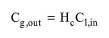
Corsi and Card (1991) also make the assumption that the VOCs in the effluent air stream are in thermodynamic equilibrium with VOCs in the influent wastewater stream, or
|
|
eq. (A.83) |
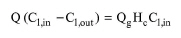
where Hc is the dimensionless Henry's constant. The combination of the above two equations yields:
|
|
eq. (A.84) |
The above equation is solved for Ci,out to calculate the concentration of VOC components in the gas outlet stream. The term Q(Ci,in-Ci,out) represents the rate of VOC emissions from a trickling filter.
1. Benefield, L.D. and Randall, C.W. 1980, Biological Process Design for Wastewater Treatment, Prentice Hall.
2. Corsi, R. L., and T. R. Card. 1991. “Estimation of VOC Emissions Using the BASTE Model,” Environmental Progress. 10: 290-299.
3. Eckenfelder, W.W., Jr., 1989, Industrial Water Pollution Control, McGraw-Hill, NY.
4. Water Pollution Control Federation, 1982, Wastewater Treatment: Plant Design, WPCF Manual of Practice No 8, Lancaster Press, PA.
The interface of this operation has the following tabs:
● Oper. Cond’s, see Trickling Filtration Operation: Oper. Conds Tab
● Reactions, see Stoichiometric Reaction/Fermentation Operation: Reactions Tab
● Vent/Emissions, see Trickling Filtration: Vent/Emissions Tab
● Labor, etc, see Operations Dialog: Labor etc. Tab
● Description, see Operations Dialog: Description Tab
● Batch Sheet, see Operations Dialog: Batch Sheet Tab
● Scheduling, see Operations Dialog: Scheduling Tab