The purpose of this model is to simulate and design an oil separation tank. In an oil separator, free oil is floated to the surface of a tank and then skimmed off. The conditions holding for the subsidence of particles apply here, except that the lighter-than-water oil globules rise through the liquid. The design of separators as specified by the American Petroleum Institute is based on the removal of all free oil globules larger than 0.015 cm.
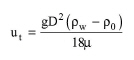
In design mode of calculation, the user specifies the rise velocity of the limiting oil globule component or provides the limiting component properties (globule diameter and density) and the viscosity of the water phase. In oil separation, the Reynolds number for the rising oil globules is usually less than 0.5 and therefore their rise velocity (ut) is governed by Stokes' law:
|
|
where:
● ρw is the density of water,
● ρ0 is the density of oil,
● μ is the viscosity,
● g is the gravity constant, and
● D is the diameter of oil globules.
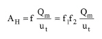
The minimum cross sectional horizontal area (AH) is then estimated by the following equation:
|
|
eq. (A.228) |
where:
● Qm is the wastewater flowrate,
● f1 is a factor that compensates for short-circuiting (usually equal to 1.2), and
● f2 is a factor that compensates for turbulence.
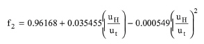
Factor f2 is given by the following empirical equation (Eckenfelder, 1989, Table 2-5):
|
|
eq. (A.229) |
where uH is the horizontal velocity which is estimated as the minimum between 15ut and 0.0152 m/s (or 3 fpm).
Then, if the tank depth, d, is specified, the required length, L, of the separator is given by:
|
|
eq. (A.230) |
Alternatively, if L is specified, the above equation can be used to calculate d. The minimum vertical cross-sectional area, Ac, is computed from the relationship:
|
|
eq. (A.231) |
In Rating Mode, the user specifies the number and dimensions of the tank(s) and the program calculates the terminal rise velocity.
The material balances are based on the removal % of the suspended components (e.g., oil globules) and the oil concentration in sludge (% v/v). The removal % is either specified by the user or calculated by the program based on the sedimentation theory. Note that you should only specify removal % for suspended components that rise to the surface. For soluble components, the amount that ends up in the oil sludge stream depends on the oil concentration that is specified by the user.
This operation may result in VOC Emissions if volatile compounds are present in the feed stream.
1. Eckenfelder, W.W. (1989). “Industrial Water Pollution Control”, Second edition, McGraw-Hill, Sect. 3-5.
The interface of this operation has the following tabs:
● Oper. Cond’s, see Oil Separation: Oper. Conds Tab
● Vent/Emissions, see Cont. Stoich. Reaction in a Photobioreactor: Vent/Emissions Tab
● Labor, etc, see Operations Dialog: Labor etc. Tab
● Description, see Operations Dialog: Description Tab
● Batch Sheet, see Operations Dialog: Batch Sheet Tab
● Scheduling, see Operations Dialog: Scheduling Tab