The purpose of this unit operation model is to simulate removal of solid particles and/or oil globules by an inclined plate separator.
● Inclined Plate (IP) Clarification Procedure
In Design Mode of calculation, a unit can be sized to remove particles with a settling velocity greater than the settling velocity of a design (limiting) particle. Alternatively, it can be sized to remove oil globules with a rise velocity greater than the rise velocity of a design (limiting) oil globule component. A third option is to design for removal of solid particles as well as oil globules.
Design for Removal of Solid Particles
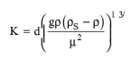
If the properties of the limiting particle component are provided, its sedimentation velocity, Vc, is estimated using a modified version of the Stokes' law (Smith and Harriott, 1993). More specifically, the K term is calculated first.
|
|
Depending on the value of K, different values are assigned to the bl and n parameters according to the table below.
|
K |
bl |
n |
|
|
||
|
=< 3.3 |
24.0 |
1.0 |
|
> 3.3 and =< 43.6 |
18.5 |
0.6 |
|
> 43.6 |
0.44 |
0.0 |
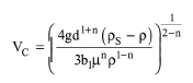
Then, the sedimentation velocity is calculated using the following equation:
|
|
where:
● g is the gravitational constant,
● ρs is the density of particle,
● ρ is the density of liquid,
● d is the diameter of design particle, and
● μ is the viscosity of fluid.
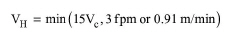
The maximum allowable mean horizontal velocity, VH, is given by:
|
|
eq. (A.205) |
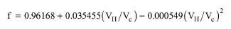
The turbulence and short-circuit (overdesign) factor, f, is calculated as a function of the ratio (VH/VC) using the following equation, which represents curve-fitting of experimental data (API Publication 421, 1989):
|
|
eq. (A.206) |
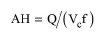
The user also has the option to specify the turbulence and short-circuit factor. Then, the horizontal area of the unit is calculated by the following equation:
|
|
eq. (A.207) |
where Q is the feed volumetric flowrate. It the calculated horizontal area exceeds the maximum (specified through the equipment tab), the program assumes multiple units operating in parallel with a total horizontal area equal to the calculated. The horizontal area of a single plate is given by:
|
|
eq. (A.208) |
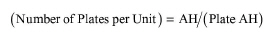
and the number of plates per unit is given by:
|
|
eq. (A.209) |
Design for Removal of Oil Globules
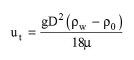
In oil separation, the Reynolds number for the rising oil globules is usually less than 0.5 and therefore their rise velocity (ut) is governed by Stokes' law:
|
|
where:
● ρw is the density of water,
● ρ0 is the density of oil,
● μ is the viscosity,
● g is the gravity constant, and
● D is the diameter of oil globules.
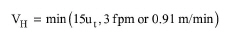
The maximum allowable mean horizontal velocity, VH, is given by:
|
|
eq. (A.211) |
The rest of the calculations are the same at those for removal of solid particles.
Design for Removal of Solid Particles as well as Oil Globules
In this case, the program calculates the settling velocity of the limiting particle component and the rise velocity of the limiting oil globule component and the sizing is done based on the minimum velocity.
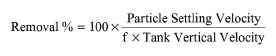
The material balances are based on the removal % of particulate and oil globule components that is specified by the user or calculated by the program. The values of ‘Oil Concentration in Oil Stream’ and ‘Solids Concentration in Sludge Stream’ determine the amount of solvent and solute components that are removed with the oil and sludge streams. The removal % of a particulate component, when not specified by the user, is calculated using the following equation:
|
|
eq. (A.212) |
In Design Mode, the Tank Vertical Velocity is equal to the settling or rise velocity that is used to size the unit. In Rating Mode, it is equal to the overflow rate (volumetric throughput divided by horizontal area). The parameter f is the turbulence and short-circuit factor. A similar equation (that utilizes the rise velocity instead of settling velocity) is used to estimate removal of oil globule components.
This operation may result in VOC Emissions if volatile compounds are present in the feed stream.
1. API Publication 421, (1989). “Monographs on Refinery Environmental Control – Management of Water Discharges – Design and Operation of Oil-Water Separators”, American Petroleum Institute, 1220 L. Street Northwest, Washington, D.C. 20005.
2. Smith J.C. and Harriott, P. (1993). “Unit Operations of Chemical Engineering”, 5th Edition, McGraw-Hill.
The interface of this operation has the following tabs:
● Oper. Cond’s, see IP Clarification: Oper. Conds Tab
● Mat. Balance, see IP Clarification: Mat. Balance Tab
● Vent/Emissions, see Cont. Stoich. Reaction in a Photobioreactor: Vent/Emissions Tab
● Labor, etc, see Operations Dialog: Labor etc. Tab
● Description, see Operations Dialog: Description Tab
● Batch Sheet, see Operations Dialog: Batch Sheet Tab
● Scheduling, see Operations Dialog: Scheduling Tab