eq. (A.224)
The purpose of this model is to simulate a dissolved-air flotation tank that separates suspended solid or liquid particles from a continuous liquid phase.
Separation is brought about by introducing fine gas (usually air) bubbles into the liquid phase. The bubbles attach to the particulate matter, and the buoyant force of the combined particle and gas bubbles is great enough to cause the particle to rise to the surface. Particles that have a higher density than the liquid can thus be made to rise. The rising of particles with lower density than the liquid can also be facilitated (e.g., oil suspension in water).
In dissolved-air flotation systems, air is dissolved in the wastewater under pressure of several atmospheres, followed by release of the pressure to the atmospheric level. In small pressure systems, the entire flow may be pressurized my means of a pump to 4 to 5 atm with compressed air added at the pump suction. The entire flow is held in a retention tank under pressure for several minutes to allow time for the air to dissolve. The pressurized flow is then admitted through a pressure-reducing valve to the flotation tank where the air comes out of solution in minute bubbles throughout the entire volume of liquid. In the larger units, a portion of the dissolved-air flotation effluent (15 to 120%) is recycled, pressurized, and semi-saturated with air. The recycled flow is mixed with the unpressurized feed stream just before admission to the flotation tank, with the result that the air comes out of solution in contact with particulate matter at the entrance of the tank.
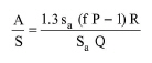
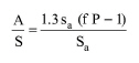
Factors that must be considered in the design of flotation tanks include the concentration of particulate matter, quantity of air used, the particle-rise velocity, and the solids-loading rate. The performance of a dissolved-air flotation system depends primarily on the ratio of the volume of air to the mass of solids (A/S) required to achieve a given degree of clarification. The relationship between the A/S ratio and the solubility of air, the operating pressure, and the concentration of sludge solids for a system in which all the flow is pressurized is given below:
|
|
eq. (A.224) |
where:
● A/S is the air-to-solid ratio (in mL air/mg solids),
● sa is the air solubility (in mL/L),
● f is the fraction of dissolved air at pressure P (usually 0.5),
● P is the pressure (in atm), and
● Sa is the solids concentration in the sludge (in mg/L).
For systems without recycle (in other words, with pressurization of the entire feed stream), the above equation is solved for P to calculate the required pressurization level.
The corresponding equation for a system with only pressurized recycle is:
|
|
eq. (A.225) |
where
● R is the pressurized recycle flowrate (in m3/day), and
● Q is the mixed-liquor feed flowrate (in m3/day).
For systems with recycle, you have the option to specify either the absolute pressure, P, or the recycle flowrate, R, as a percent of the feed flowrate and the above equation is used to calculate R or P, respectively.
The material balances are based on the removal (flotation) % of particulate components and the particulate concentration in sludge (in mg/liter). Note that you should only specify removal % for particulate components. For soluble components, the amount that ends up in the sludge stream depends on the sludge concentration that is specified by the user.
This operation may result in VOC Emissions if volatile compounds are present in the feed stream.
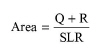
In design mode of calculation, the cross sectional area of the flotation tank is calculated by dividing the combined flowrate to the unit, (Q+R), by the surface loading rate, SLR.
|
|
eq. (A.226) |
The surface loading rate, SLR, detention time, td, and basin depth, d, are related as follows:
|
|
eq. (A.227) |
The above equation is used to calculate the basin depth when the detention time is specified and vice-versa.
In Rating Mode, the user specifies the number and size of basins and the program calculates the surface loading rate.
1. Tchobanoglous G. and F.L. Burton (1991). “Wastewater Engineering: Treatment, Disposal, and Reuse”, Third edition, Metcalf & Eddy, Inc., McGraw-Hill, Sect. 6-7.
2. Eckenfelder, W.W. (1989). “Industrial Water Pollution Control”, Second edition, McGraw-Hill, Sect. 3-5.
The interface of this operation has the following tabs:
● Oper. Cond’s, see Flotation: Oper. Conds Tab
● Vent/Emissions, see Cont. Stoich. Reaction in a Photobioreactor: Vent/Emissions Tab
● Labor, etc, see Operations Dialog: Labor etc. Tab
● Description, see Operations Dialog: Description Tab
● Batch Sheet, see Operations Dialog: Batch Sheet Tab
● Scheduling, see Operations Dialog: Scheduling Tab