eq. (A.65)
This unit operation model simulates transformation (e.g., bio-oxidation, chemical oxidation, hydrolysis, photolysis, nitrification, sorption, etc.) of organic and other compounds in a well-mixed tank under aerobic conditions. Any number of reactions can be specified with a variety of kinetic expressions. The stoichiometry of a reaction is specified on a mass or molar basis while the reaction rate is specified by selecting appropriate expressions for the substrate term, the other term (e.g., oxygen), and the biomass term. The reaction rate constant is either specified by the user or retrieved from the component databank for biochemical oxidation reactions that follow Monod-type of kinetics. The various reactions may be based on different biomass components. For instance, heterotrophic biomass may be used for biochemical oxidation reactions and autotrophic biomass for nitrification reactions. Biomass death and hydrolysis reactions may be written to keep track of the active and dead fractions of biomass components.
● Kinetic Well-Mixed (WM) Aerobic Bio-Oxidation Procedure
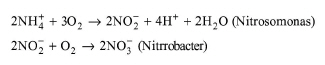
Nitrification is the biological oxidation of ammonia to nitrate with nitrite formation as an intermediate. Nitrification may occur in aeration basins along with other oxidation reactions if the sludge residence time is large enough to prevent wash out of the nitrifying microorganism. The microorganisms involved are the autotrophic species Nitrosomonas and Nitrobacter, which carry out the reaction in two steps (Eckenfelder, 1989):
|
|
eq. (A.65) |
The rate of nitrification has been reported in the literature (Wong-Chong and Loeht, 1975) as essentially constant with overall biomass concentrations (as VSS) up to 1500 mg/l and decreases above that level. An average nitrification rate, at 20 °C, is around 1.04 mg NH3-N oxidized per milligram of nitrifying microbial mass per day. Note that it is easy to express nitrification rates based on nitrifying biomass (autothrophs) if you specify a component (during component initialization) representing nitrifying biomass. Like all biochemical reactions, the rate of nitrification is temperature-dependent with q in the range of 1.03 to 1.15.
The aeration basin model handles VOC emission calculations. Different models exist for surface and diffused aeration that are mass transfer and equilibrium limited, respectively.
In terms of sorption, you may specify the fraction of a component that adsorbs on the primary biomass component. The program, then, keeps track of the fraction in solution throughout the process with the ‘Extra-Cell %’ term. The ‘Extra-Cell %’ term represents the percentage of a component that is in solution while 100 - Extra-Cell% represents the adsorbed portion of a component.
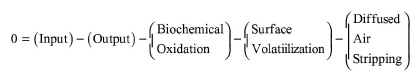
For steady-state operation of an aeration basin, the general material balance equation for a component that biodegrades and is emitted is given by the following equation:
|
|
eq. (A.66) |
or
|
|
eq. (A.67) |
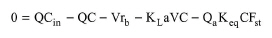
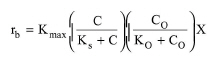
where Q is the liquid flow rate, V is the reactor volume, Cin is the inlet concentration, C is the outlet concentration which is the same as the concentration in the reactor, rb is the biodegradation rate, KLa is the overall mass transfer coefficient, Qa is the air flow rate (in case of diffused aeration), Keq is the equilibrium constant, and Fst is the saturation term (it represents the extent of saturation of the exiting gas stream). In general, the biodegradation rate is a function of substrate concentration, oxygen concentration, and biomass concentration. Various expressions are available for the effect of substrate. The overall equation with a Monod-type substrate expression is written as follows:
|
|
where Kmax is the maximum rate constant, Ks is the half saturation constant for the substrate, C0 is the oxygen concentration, K0 is the half saturation constant for oxygen, and X is the biomass concentration. Alternative expressions for the substrate and oxygen terms are also available. The component databank includes data for Kmax and Ks for a large number of chemical components.
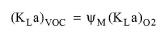
The overall mass transfer coefficient of a VOC component is estimated as a function of the oxygen mass transfer coefficient in wastewater, using a proportionality coefficient, ψM. In other words,
|
|
eq. (A.69) |
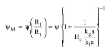
The value of (KLa)O2 in the wastewater is a user input to the program. The value of ψM is given by the following equation (Hsieh et al., 1993):
|
|
where ψ is the dimensionless transfer coefficient proportionality constant, HC is Henry's law constant, and kga and kla are the individual mass transfer coefficients (in s-1) of the VOC in the gas and liquid phases, respectively. The value of ψ is calculated by the following equation (Corsi and Card, 1991):
|
|
eq. (A.71) |
where DVOC and DO2 are the liquid diffusion coefficients (in m2/s) for a VOC and oxygen, respectively. The exponent n varies from 0.5 for penetration and surface renewal theories to 1.0 for two-film theory (Corsi and Card, 1991) and is typically 0.5 to 0.6 (Mihelcic et al., 1993). The diffusion coefficients of VOC components are retrieved from the component databank of the program.
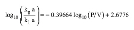
For mechanically aerated systems, the value of the (kga/kla) ratio is estimated using the following empirical equation (Hsieh et al., 1993):
|
|
eq. (A.72) |
where (P/V) represents the mechanical power consumed for surface aeration divided by the liquid volume of the aeration basin and it is calculated by the program. Alternatively, you have the option to set the value of (kga/kla) or set the value of the term in parentheses in eq. (A.70) (called ‘Rl/Rt’ in the ‘Emission Model’ dialog of a component, see Agitated Tank Operations: Vent/Emissions Tab).
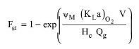
For diffused aerated systems, the Fst term is calculated by the following equation:
|
|
eq. (A.73) |
As previously, you have the option to set either the value of the (kga/kla) ratio or the term Rl/Rt in order to calculate ψM.
The equilibrium constant is estimated by:
|
|
eq. (A.74) |
where R is the universal gas constant and T is the temperature.
The above equations written for each chemical component entering an aeration basin constitute a set of non-linear equations, which is solved numerically to calculate the exit concentration and the emission rate of each component.
See Vessel Sizing (Continuous Operations).
See Vacuum Pump Auxiliary Equipment Calculations.
1. Corsi, R. L., and T. R. Card. 1991. “Estimation of VOC Emissions Using the BASTE Model,” Environmental Progress. 10: 290-299.
2. Eckenfelder, W.W., Jr., 1989, Industrial Water Pollution Control, McGraw-Hill, NY.
3. US EPA, 1975, Process Design Manual for Nitrogen Control.
4. Hsieh, C.-C., K. S. Ro, and M. K. Stenstrom, “Estimating Emissions of 20 VOCs. I: Surface Aeration, II: Diffused Aeration”, J. of Env. Engr., Vol. 119, No. 6, Nov./Dec. 1993, ASCE, ISSN 0733-9372.
5. Mihelcic, J. R., C. R. Baillod, J. C. Crittenden, and T. N. Rogers. 1993. “Estimation of VOC Emissions from Wastewater Facilities by Volatilization and Stripping,” Journal of Air and Waste Management Association. 43: 97-105.
6. Melcer, H, J. P. Bell, D. J. Thomas, C. M. Yendt, J. Kemp, and P. Steel. 1994. “Modeling Volatile Organic Contaminants' Fate in Wastewater Treatment Plants,” Journal of Environmental Engineering. 120: 588-609.
7. Melcer, H. 1994. “Monitoring and Modeling VOCs in Wastewater Facilities,” Environmental Science and Technology. 28: 328A-335A.
8. Tchobanoglous G. and F.L. Burton (1991). “Wastewater Engineering: Treatment, Disposal, and Reuse”, Third edition, Metcalf & Eddy, Inc., McGraw-Hill, Sec. 10-1.
9. Wong-Chong, G.M., and R.C. Loeht: Water Res., vol. 9, p. 1099, 1975.
The interface of this operation has the following tabs:
● Oper. Cond’s, see Aerobic Bio-Oxidation Operations: Oper. Conds Tab
● Volumes, see Continuous Vessel Operations (Design Mode): Volumes Tab and Continuous Vessel Operations (Rating Mode): Volumes Tab
● Reactions, see Environmental Reaction Kinetics Dialog
● Vent/Emissions, see Agitated Tank Operations: Vent/Emissions Tab
● Sorption, see Environmental Reaction Operations: Sorption Tab
● Labor, etc, see Operations Dialog: Labor etc. Tab
● Description, see Operations Dialog: Description Tab
● Batch Sheet, see Operations Dialog: Batch Sheet Tab
● Scheduling, see Operations Dialog: Scheduling Tab
For details on the kinetics of the environmental reactions, see Environmental Reaction Kinetics Dialog.