eq. (A.213)
The purpose of this unit operation model is to simulate the performance of a clarification and thickening basin.
The material balances are based on the removal percentage of particulate components and the solids concentration in sludge (in mg/L). Note that you should only specify removal % for particulate components. The amount of liquid and soluble components in the sludge stream is determined from the sludge solids concentration.
This operation may result in VOC Emissions if volatile compounds are present in the feed stream.
In Design Mode, the user specifies the feed volumetric loading rate in m3/m2-day or selects a solids flux model that utilizes the sludge volume index (SVI). When the feed volumetric loading rate is specified, the sedimentation area (cross sectional area of the basin) is calculated by dividing the feed flowrate by the loading rate. If the calculated surface area exceeds the maximum, the program assumes multiple units in parallel with a total surface area equal to the calculated.
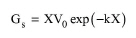
The solids flux models for equipment sizing are based on the limiting solids settling flux theory. In general, solids are transported to the bottom of a thickener by the settling velocity component (gravity flux) and the velocity component due to withdrawal in the underflow (underflow flux). The following empirical equation relates the gravity flux to the solids concentration and the SVI:
|
|
eq. (A.213) |
where Gs is the solids gravity flux (kg/m2-h), X is the concentration of suspended solids (kg/m3), and V0 (m/h) and k (m3/kg) are adjustable parameters that depend on SVI.
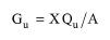
The underflow solids flux (Gu) is given by the following equation:
|
|
eq. (A.214) |
where Qu is the underflow volumetric flowrate (m3/h), and A is the cross-sectional area of the thickener (m2).
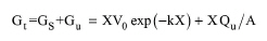
The total flux (Gt) is the sum of Gs and Gu:
|
|
The figure below displays the solids gravity flux, underflow flux, and total flux as a function of solids concentration. The limiting solids flux, GL=Gt(XL), which is used to calculate the area of the sedimentation basin, corresponds to the minimum value of the total flux.
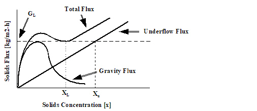
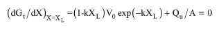
There are two unknowns in eq. (A.215): the solids concentration X and the Qu/A ratio. Therefore, we need two independent equations to solve the problem. Since GL corresponds to the minimum value of Gt, the first equation is derived by differentiating Gt with respect to X, setting the derivative at XL equal to zero and solving for Qu/A:
|
|
eq. (A.216) |
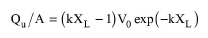
or:
|
|
eq. (A.217) |
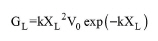
By substituting Qu/A from the above equation into eq. (A.215), we get GL as a function of XL:
|
|
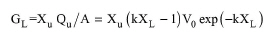
The second equation is derived by observing in the above figure that at some concentration Xu, Gu is equal to GL. Therefore:
|
|
eq. (A.219) |
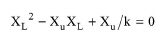
Combining the above two equations results in the following quadratic equation with respect to XL:
|
|
eq. (A.220) |
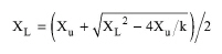
The positive root of the above quadratic equation is given by:
|
|
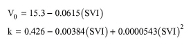
In the above equations, parameters V0 and k can be either specified or calculated based on the specified SVI index. Two different models have been implemented for calculating V0 and k as a function of SVI. The first one is the model of Daigger and Roper (1985):
|
|
eq. (A.222) |
This model was validated for SVI values in the range of 36 to 402 [mL/g].
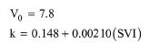
The second model is that of Wahlberg and Keinath (1988, 1990):
|
|
eq. (A.223) |
This model was validated for SVI values in the range of 35 to 220 [mL/g].
|
|
Both of these models were derived for solids concentrations of up to 15 g/L. Based on our testing, concentrations higher than 12 g/L lead to very low solids flux and result in excessively high sedimentation areas. |
The solids settling flux algorithm in SuperPro Designer consists of the following steps:
1. V0 and k, if not specified by the user, are calculated using one of the above models.
2. XL is calculated from eq. (A.221) based on the specified value for the solids concentration in sludge (Xu).
3. The limiting solids flux, GL, is calculated from eq. (A.218).
4. The required area, A, of the sedimentation tank is calculated by dividing the solids mass flowrate in the underflow (based on the removal % of particulate components), XuQu, by the limiting solids flux, GL.
5. The material balances are completed based on the removal % of particulate components and the specified underflow solids concentration, Xu.
6. In Rating Mode, the user specifies the number and size of basins and the program calculates the specific feed loading rate. The flux models play no role in rating mode.
1. Tchobanoglous G. and F.L. Burton (1991). “Wastewater Engineering: Treatment, Disposal, and Reuse”, Third edition, Metcalf & Eddy, Inc., McGraw-Hill, Sect. 6-5.
2. Daigger, G.T. and R.E. Roper (1985). “The relationship between SVI and activated sludge settling characteristics”, Journal WPCF, Vol. 57, No. 8, pp. 859-866.
3. Whalberg, E.J. and T.M. Keinath (1988). “Development of settling flux curves using SVI”, Journal WPCF, Vol. 60, No. 12, pp. 2095-2100.
4. Keinath, T.M. (1990). “Diagram for designing and operating secondary clarifiers according to the thickening criteria”, Research Journal WPCF, Vol. 62, No. 3, pp. 254-258.
The interface of this operation has the following tabs:
● Oper. Cond’s, see Thickening: Oper. Conds Tab
● Vent/Emissions, see Cont. Stoich. Reaction in a Photobioreactor: Vent/Emissions Tab
● Labor, etc, see Operations Dialog: Labor etc. Tab
● Description, see Operations Dialog: Description Tab
● Batch Sheet, see Operations Dialog: Batch Sheet Tab
● Scheduling, see Operations Dialog: Scheduling Tab