eq. (A.336)
A cooling tower is used as a specialized heat exchanger; the two fluids involved are water and air. During this operation water is sprayed into the tower from the top while ambient air enters through the side-wall (crossflow configuration). A fraction of the sprayed water is vaporized due to evaporative cooling, resulting in mass and heat transfer from the water to the air stream. The modeling of the cooling tower operation is very specific to this process, and calculations may not be performed or, if performed, may be inaccurate for large deviations from typical cooling tower operating conditions.
The inlet water stream, may contain some contaminants. If these contaminants are volatile, emission calculations can be performed. However, if the composition of the inlet water stream is specified such that the mass fraction of the selected pure component representing water is less than 95%, the calculations may not be accurate, although they will still be performed. Similarly, if the nitrogen and oxygen composition of the inlet air stream differs significantly from that of typical ambient air, the calculations may also be inaccurate, even though they will still be carried out.
A fraction of the sprayed water may be lost in the form of drift (small water droplets entrained in the air moving upward). Also, a fraction of the cold water after cooling may be discharged through the blowdown stream. Lastly, if a makeup stream exists, makeup water will be added to the cold water to replenish losses from drift, evaporation, and blowdown.
● Cooling in a Cooling Tower Procedure
A percentage of the inlet (hot) water flow, equal to the specified drift percentage, is directed to the Drift stream. The remainder of the water is subjected to evaporative cooling.
Evaporative Cooling
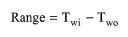
The model is based on a classical treatment of cooling tower design (with the basic assumptions), as described in references 1-3. The Cooling Tower Range is calculated as:
|
|
eq. (A.336) |
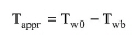
where TwI and TwO are the hot and cold water temperatures, respectively. The Approach Temperature (Tappr) is calculated as:
|
|
eq. (A.337) |
where Twb is the air wet bulb temperature.
The water-to-air mass flow ratio (r=L/G) is set by the user in design mode and calculated in rating mode. The water mass flow rate (L) is taken from the inlet water stream. Based on these values, the model calculates the air mass flow rate (G). From this, the actual inlet air stream flow is derived and propagated backward through the network of connectivity.
The maximum water-to-air ratio (rmax) for feasible cooling tower operation is calculated using a graphical method based on the above variables (as described in references 1-3). In design mode, if the specified water-to-air ratio exceeds rmax, a warning message is displayed, prompting the user to reduce the ratio.
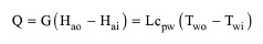
The energy balance for evaporative cooling is represented by the following equation:
|
|
eq. (A.338) |
where Q is the cooling duty, Hai and Hao are the enthalpies of air before and after cooling, respectively, and cpw is the specific heat capacity of water. To calculate the enthalpy of air as a function of its temperature and humidity, psychometric equations are used (see reference 5).
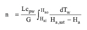
In design mode, the enthalpy of air after cooling (Hao) is obtained from the energy balance. The theoretical number of stages (n), or tower characteristic integral, is calculated by numerical integration of the Merkel equation:
|
|
eq. (A.339) |
where
● Tw is the water temperature at the air-water interface (calculated from the energy balance based on air enthalpies before and after evaporation), and
● Ha,sat is the saturation enthalpy of air at Tw.
Since this integral is applicable to counter-current configurations, a correction factor is applied for crossflow configurations (see reference 4). The calculated number is used for sizing calculations.
In rating mode, the L/G ratio is determined by simultaneously solving the Merkel equation and sizing correlations. The enthalpy of air after evaporation (Hao) is then calculated from the energy balance. In addition, the water loading flux is calculated by dividing the calculated inlet water volumetric flowrate by the total floor area of all units.
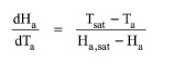
The air temperature after evaporative cooling (Tao) is calculated through numerical integration of the following equation:
|
|
eq. (A.340) |
where
● Ha and Ta are the enthalpy and temperature of air, respectively, and
● Tsat and Ha,sat are the respective temperature and enthalpy of air at the air-water interface.
The above equation is derived from a combination of the heat and a mass transfer balances and the Lewis relations. Therefore, it is only valid for water-air systems (see reference 1-2). At the air-water interface, it is assumed that the temperature of air is equal to the temperature of water and the enthalpy of air is equal to the enthalpy of saturated air. Psychrometric equations are used to calculate the humidity of the air before and after evaporative cooling (Ywi and Ywo). In order to obtain Tsat and Ha,sat for every given air temperature, the energy balance and the psychrometric equations are used.
The water uptake of the air stream represents the water evaporation rate. The air and water pressures after evaporative cooling are assumed equal to the ambient pressure.
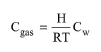
Assuming the air after evaporative cooling is in equilibrium with the inlet (hot) water, the concentration of a volatile component in the output air is calculated as:
|
|
eq. (A.341) |
where:
● Cgas is the component’s molar concentration in the air after evaporative cooling,
● Cw is the component’s molar concentration in the inlet (hot) water,
● H is the component’s Henry’s constant (in L.atm/mol),
● R is the universal gas constant, and
● T is temperature.
A percentage of the cold water after evaporative cooling, equal to the specified blowdown percentage, is discharged through the blowdown stream. The remaining water is either mixed with makeup water (if available) or sent to the pump (if included) or the Water Out stream.
If a makeup water stream exists, the program calculates the required flow of makeup water to compensate for losses from drift, evaporation, and blowdown. The makeup water is mixed adiabatically with the cold water, with the pressure of the mixture assumed equal to the ambient pressure. This mixture is then either sent to the pump (if included) or the Water Out stream.
If a cold water pump is included, the cold water is mixed with makeup water (if available), and the mixture is sent to the pump. The pressure after the pump is assumed equal to the ambient pressure (i.e., the pressure increase by the pump is assumed equal to the pressure drop in the pump, resulting in zero net pressure change). The pump’s power consumption is calculated by multiplying the mixture’s volumetric flowrate by the specified pressure change and then dividing by the specified efficiency. After pumping, the mixture is sent to the Water Out stream.
If an induced draft fan is included, the air after evaporative cooling is mixed with drift and volatile emissions (if any), and the mixture is sent to the fan. The pressure after the fan is assumed equal to the ambient pressure (i.e., the pressure increase by the fan is assumed equal to the pressure drop in the fan, resulting in zero net pressure change). The fan’s power consumption is calculated by multiplying the mixture’s volumetric flowrate by the specified pressure change and then dividing by the specified efficiency. After the fan, the mixture is sent to the Air Out stream.
In design mode, the user specifies the water loading flux (the ratio of the water volumetric flow rate to the tower floor area), and the program calculates the required tower floor area for the operation. If the required floor area does not exceed the specified maximum floor area, a single unit will be used. However, if it exceeds the maximum floor area, multiple units are assumed to operate in parallel so that the total floor area of all units matches the required floor area for this operation. Additionally, the packing height is calculated based on the calculated tower characteristic integral (theoretical number of stages), using correlations for wood-splash bar packed towers (see reference 4).
In rating mode, the user specifies the number of units as well as the tower floor area and packing height for each unit. Based on these values, the program calculates the water loading flux, tower characteristic integral, and water-to-air ratio. If the calculated water loading flux is lower than 3 m3/m2-h, a warning is displayed because the results may not be reliable due to poor distribution. Similarly, if the calculated water loading flux is higher than 22.5 m3/m2-h, a warning is displayed because the results may not be reliable due to flooding.
1. Wankat, P.C. (1988). Equilibrium Staged Separations, Elsevier.
2. W.L. MacCabe, Smith, J.C, and Harriot, P. (1993). Unit Operations of Chemical Engineering, McGraw-Hill.
3. R.H. Perry and Green, D.W. (1999). Perry’s Chemical Engineers’ Handbook, McGraw-Hill.
4. A.K.M. Mohiuddin and Kant K. (1996). Int J. Refrig., 19(1), pp43-60.
5. Phychometrics, ASHRAE Handbook of Fundamentals, ASHRAE, Atlanta, GA.
The interface of this operation has the following tabs:
● Oper. Cond’s, see Cooling in a Cooling Tower: Oper. Conds Tab
● Vent/Emissions, see Cooling in a Cooling Tower: Vent/Emissions Tab
● Labor, etc, see Operations Dialog: Labor etc. Tab
● Description, see Operations Dialog: Description Tab
● Batch Sheet, see Operations Dialog: Batch Sheet Tab
● Scheduling, see Operations Dialog: Scheduling Tab