Junction boxes combine wastewater streams prior to entering a treatment plant.
● Junction Box Mixing Procedure
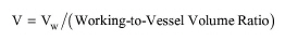
In Design Mode of calculation, the user specifies the residence time (tR) and the working to vessel volume ratio. The working (liquid) volume (Vw) and the vessel volume (V) are calculated using the following equations:
|
|
|
|
where F is the feed volumetric flowrate. Dividing the vessel volume by the tank depth yields the tank surface area. If the calculated surface area exceeds its maximum possible value (specified through the Equipment tab), the program assumes multiple, identical units operating in parallel with a total surface area equal to the calculated.
In Rating Mode, the user specifies the vessel area and depth, the number of units, and the working to vessel volume ratio and the program calculates the residence time.
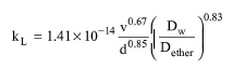
Junction boxes are usually open to the atmosphere and VOC emissions occur in the same manner as emissions from quiescent surface tanks (for a detailed description of the emission calculations from quiescent tanks, see Clarification: Modeling Calculations), except that the liquid phase mass transfer coefficient is given by the following empirical equation (EPA, 1994):
|
|
eq. (A.330) |
where:
● v is the wastewater velocity (in cm/s),
● Dw is the diffusivity of the VOC component in water, and
● Dether is the diffusivity of ether (reference component) in water.
The wastewater velocity is calculated by dividing the wastewater volumetric flowrate by the depth, d, of the liquid inlet flow into the junction box and the width of the junction box (or, the square root of the area of the liquid surface).
The depth, d, can be estimated in two different ways depending on the location of the inlet pipe. If the pipe is submerged below the surface of the wastewater, the depth is equal to the pipe's internal diameter plus the distance the pipe is submerged under the surface of the liquid in the junction box. If the location of the wastewater discharge is at the surface of the liquid in the junction box, then the depth of flow is considered to be half of the pipe's internal diameter.
The calculation of the gas phase mass transfer coefficient, kg, as well as the rest of the VOC emission calculations are identical to those of the Clarification Operation; for more details, see Clarification: Modeling Calculations.
1. U. S. Environmental Protection Agency (EPA). 1994. “Air Emissions Models for Waste and Wastewater,” Rep. EPA-453/R-94-080A. Research Triangle Park, NC: Office of Air Quality Planning and Standards.
The interface of this operation has the following tabs:
● Oper. Cond’s, see Junction Box Mixing: Oper. Conds Tab
● Vent/Emissions, see Junction Box Mixing: Vent/Emissions Tab
● Labor, etc, see Operations Dialog: Labor etc. Tab
● Description, see Operations Dialog: Description Tab
● Batch Sheet, see Operations Dialog: Batch Sheet Tab
● Scheduling, see Operations Dialog: Scheduling Tab