eq. (A.7)
Use this operation to simulate distillation in a batch distillation unit.
● Batch Distillation Procedure
● Batch Vessel Procedure in a Reactor
● Batch Vessel Procedure in a Seed Reactor
● Batch Vessel Procedure in a Bioreactor
● Batch Vessel Procedure in a Seed Bioreactor
● Batch Vessel Procedure in a Disposable Bioreactor
● Batch Vessel Procedure in a Disposable Seed Bioreactor
● Batch Vessel Procedure in a Fermentor
● Batch Vessel Procedure in a Seed Fermentor
● Batch Vessel Procedure in a Disposable Bioreactor
● Inoculum Preparation Procedure in a Rocking Bioreactor
● Inoculum Preparation Procedure in a Roller Bottle
● Inoculum Preparation Procedure in a T-Flask
● Inoculum Preparation Procedure in a Shake Flask
● Inoculum Preparation Procedure in a Test Tube
● Batch 3x3 Generic Box Procedure
● Batch 5x5 Generic Box Procedure
● Batch 10x10 Generic Box Procedure
The batch distillation unit is modeled as a fast, accurate short-cut batch distillation simulation based on the equations of continuous distillation. This method takes advantage of the fact that, at any snapshot in time, the batch distillation column resembles the rectification section of a continuous column. Therefore, the short-cut design methods which have been successfully applied in the simulation of continuous distillation columns are used at every time step in batch distillation. The short-cut method for the simulation of continuous distillation columns used is the Fenske-Underwood-Gilliland (FUG) method. This common empirical method, used to determine reflux and stage requirements of multi-component continuous distillations, was chosen due to its ease of use and proven applicability.
The pot of the batch distillation unit is sized as a reactor-type of vessel. In design mode of calculation, the working volume is set equal to the volume of material processed per cycle. Dividing the working volume by the initial ‘Working/Vessel Volume’ ratio yields the vessel volume. If the calculated vessel volume excess the max. vessel volume, then multiple units of equal size are assumed with a total volume equal to the calculated vessel volume. In rating mode, the pot volume is specified by the user and the program calculates the initial and final working to vessel volume ratio. If either the initial or the final working/vessel ratio is not between and min and max limits, the user is warned.
The distillation time can be set by the user or calculated by the model. In the case where the distillation time is calculated by the program, the user must provide the vaporization rate (in kmol/h or L/h) for each operating period. When the distillation time is set by the user, the model reports an average vaporization rate (in kmol/h) for all operating periods.
The relative volatilities of the various components are either specified by the user or calculated by the program assuming ideal solutions and using Antoine’s equation for estimating vapor pressures. Non-volatile components (specified by checking the Non-Volatile? checkbox) do not participate in vapor-liquid equilibrium calculations and exit the unit through the bottoms stream. If you use the default relative volatility values of one, equal amounts of each volatile component will end up in the distillate stream(s).
Up to five operating periods (or cuts) can be specified. Each cut can represent a desired product or an intermediate fraction. For each operating period, you specify a constant reflux ratio and the mole percentage of the total non-volatile components (that are initially fed into the system) distilled in that period.
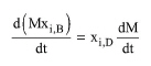
The short-cut algorithm consists of an outer loop that steps forward in distillation time and an inner loop that solves the FUG equations at each time step. For the outer loop, the differential balances for total mass in the pot and for each component can be written as follows:
|
|
eq. (A.7) |
|
|
eq. (A.8) |
where V is the vapor rate and R is the reflux ratio in that operating period.
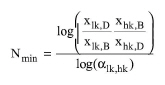
The inner loop uses the pot compositions and amount, the vapor rate of the column, the number of stages and the reflux ratio to solve the FUG equations to compute the overhead vapor composition. First, Fenske’s equation
|
|
eq. (A.9) |
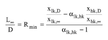
is used to compute the minimum number of stages. For batch distillation, the pinch has to occur in the rectifying section of the column. Underwood’s equations
|
|
eq. (A.10) |
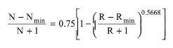
are applied to find the pinch point in the rectifying section of the column. Gilliland’s equation
|
|
eq. (A.11) |
is used next to relate the minimum number of stages, the minimum reflux ratio, the actual number of stages and the actual reflux ratio. The final equation solved in the inner loop states that the sum of the overhead molar fractions be equal to unity.
The short-cut model works best for simulating columns under the assumptions of constant molar vapor rate during a period and ideal thermodynamics. The assumption being that, at every time step, the liquid and vapor at every stage in the batch column are in equilibrium. The algorithm further assumes that all volatile components distribute to both the distillate and the bottoms, making it a Class 1 separation. If a component is to appear only in the bottom, make sure you specify it as non-volatile.
The current batch distillation algorithm does not perform energy balances. The condenser and final bottoms temperature that are specified by the user are simply used to set the temperatures of the outlet streams.
The equipment purchase cost includes the cost of the pot vessel as well as the cost of the column and its trays.
The batch distillation unit can generate profiles of component concentration (in the receiver, the distillate, and the bottoms) as a function of time. The initialization of recorded data is done through the ‘Profiles’ tab shown below. The user has flexibility in specifying the number of recorded data sets, identifying the streams and components for which compositions are recorded, and selecting the units of recorded variables.
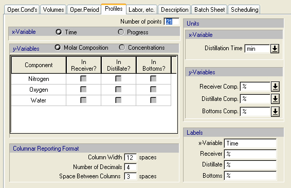
Profiles Tab - the above dialog is used to initialize concentration profiles in a batch distillation.
The recorded data sets can be viewed in tabular format and saved in a file in ASCII or Excel (tab-delimited ASCII) format. Then, the plotting capabilities of Excel (or some other plotting software package) can be used to display the data graphically.
► In order to view or save the recorded data sets in tabular format you must do the following steps:
1. Right-click on the unit procedure’s icon (e.g. a batch distillation unit).
2. From the drop-down menu that is displayed, choose Dynamic Data Records.
3. From the list of available operations that pops-up, choose the desired operation name (e.g. DISTILL-1).
4. Choose View as Table to view the data (see figure below) or Save in an Ascii Formatted File to save the data in ASCII format, or Save in an Excel Formatted File to save the data in Excel (tab-delimited ASCII) format.
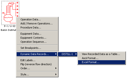
The Dynamic Data Records drop-down menu that is displayed when the user right-clicks on a procedure that hosts a batch distillation operation. The top line allows user to view the recorded data and the other two to save the recorded data in a formatted file
|
|
In order to preserve certain formatting aspects in the display of the results (e.g., in Notepad), it is recommended that the Consolas or Lucida Console font should be employed. |
1. S. Sundaram (1992). Development of a Fast, Accurate Short-Cut Model for Batch Distillation Simulation, PhD Thesis, Dept. of Chemical Engineering, MIT, Cambridge, MA.
2. U. M. Diwekar (1995). BATCH DISTILLATION: Simulation, Optimal Design and Control, Taylor & Francis Publ., Bristol, PA.
The interface of this operation has the following tabs:
● Oper. Cond’s, see Batch Distillation: Oper. Conds Tab
● Volumes, see Batch Vessel Operations: Volumes Tab
● Oper. Period, see Batch Distillation: Oper. Period Tab
● Profiles, see Batch Distillation: Profiles Tab
● Labor, etc, see Operations Dialog: Labor etc. Tab
● Description, see Operations Dialog: Description Tab
● Batch Sheet, see Operations Dialog: Batch Sheet Tab
● Scheduling, see Operations Dialog: Scheduling Tab