Auxiliary Equipment
Besides the main equipment that are assumed to be hosting all unit procedures in a process, there may be other equipment that provide support in order to execute certain operations. For example, a Clean-in-Place operation requires the use of a CIP skid which engages for the entire duration of the operation. Oftentimes, the availability of such skids may be a critical issue in the planning and scheduling of a process. Another example of a supporting (auxiliary) hardware may be the presence of a transfer line (Transfer Panel) that engages every time material needs to be moved from one location (equipment) to another. Once again, there may be a limited number of available transfer panels or connection lines and therefore the timing of operations that need to engage them may need to be adjusted appropriately such that there are no conflicts (overlapping use) of such facilities. Vacuum pumps are also commonly engaged to achieve sub-atmospheric pressures in vessels during venting or gas sweep to remove fumes from the contents of a vessel.
Auxiliary Equipment Types
The ‘Designer’ (or System) database contains the definition of four predefined or built-in auxiliary equipment types:
● CIP Skid,
● SIP Panel,
● Transfer Panel, and
● Vacuum Pump.
Understanding that in specific simulations, there may be other types of auxiliary equipment needed (e.g. Chromatography skids that accompany most chromatographic operations, polish filters attached outgoing or incoming material transfer lines, blowers, etc.) SuperPro Designer allows the user to extend the concept of auxiliary equipment by allowing the user to introduce his/her own user-defined auxiliary equipment type(s). Once a newly defined type is established, users can create specific instances of these equipment and associated them with the operation of their choice. An auxiliary equipment of one of the four built-in types (see above) when introduced can be in either ‘Rating’ or ‘Design’ mode; in other words, their size can either be set by the user upon introduction, or their size can be calculated based on their utilization by all the operations in a process model. Each auxiliary equipment may use a different variable to represent its size: e.g. CIP skids use capacity (volume) as their size variable, but transfer panels use throughput. If a built-in type auxiliary equipment is introduced in ‘Rating’ mode (i.e., with a given size) during simulation the application will determine based on the utilization of the equipment if there’s enough ‘size’ to accommodate all the needs of the servicing operation or if there’s a size violation. Please note that the user-defined types of auxiliary equipment, can still be characterized by a ‘size’ variable as part of their definition, but they can only be in ‘Rating’ mode (i.e. they can’t be sized by the operations that utilize them). Furthermore, since SuperPro cannot possibly know the nature of their ‘size’ variable and how it is affected by the performance of the engaging operation, the simulation engine cannot warn about possible size violations for non built-in types of auxiliary equipment. Essentially, the only benefit for introducing such auxiliary equipment types, is to:
a) Capture utilization and discover possible sharing violations, and
b) Capture purchase cost and/or consumable costs associated with their engagement.
To access the Auxiliary Equipment Types Definition dialog, click } } from the main menu of the application. From this dialog, you can add a new auxiliary equipment type to the “User” database, delete an existing auxiliary equipment type in the “User” database, or view/edit the properties of an existing auxiliary equipment type. Please note that once a user-defined auxiliary equipment type is introduced its ‘size’ variable definition cannot be changed.
Introduce a New Auxiliary Equipment
To introduce a new auxiliary equipment (of a given type either built-in or user-defined), you must visit the Auxiliary Equipment dialog. This dialog appears when you click } } or } } from the main menu, or when you right-click on an empty space of the flowsheet and then click } from the flowsheet’s context menu. From this interface, you may add a new auxiliary equipment of an existing type (e.g., CIP Skid, SIP Panel, Transfer Panel, Vacuum Pump, or of a user-defined type), view the locations where a selected auxiliary equipment is used, delete a selected auxiliary equipment, or view/edit the properties of a selected auxiliary equipment. Each of the built-in auxiliary equipment types features its own definition dialog since each has its own special features recognized by the application (see later in the chapter). The user-defined auxiliary equipment types, all share a common definition dialog (see Auxiliary Equipment Dialog).
If you double-click on a selected auxiliary equipment, Auxiliary Equipment Dialog is displayed.
|

|
A specific auxiliary equipment can either be introduced first (as described above) and then be engaged at the operation that requires it or it can be introduced directly at the operation interface that requires it. Typically, built-in type auxiliary equipment’s engagement appears on the operation’s “Oper.Cond’s” tab (for CIP skids, SIP panels & vacuum pumps required to maintain a set vacuum operating pressure), or the “Vent/Emissions” tab (if a vacuum pump is needed to maintain vacuum). Transfer panels are usually engaged in the “Labor, etc.” tab of an operation’s i/o dialog. Finally, the user-defined auxiliary equipment are always engaged through the “Labor, etc.” tab of an operation’s i/o dialog.
|
If you no longer need the presence of an auxiliary equipment, you can delete it from a process model by visiting the Auxiliary Equipment Dialog or from Process Explorer interface (‘Aux.Equip’ tab). Deleting an auxiliary equipment will automatically disengage it from all the operations that it was previously assigned.
Auxiliary Equipment Sharing Violations
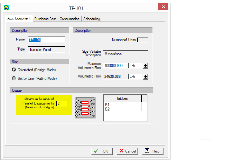
Every auxiliary equipment, includes as part of its definition a “Max Number of Engagements” allowed. Unlike main equipment that of course can only be hosting one procedure at a time, auxiliary equipment (like Transfer Panels) could be servicing more than operations at the same time. For example, in Number of Maximum Allowed Engagements for a Transfer Panel. below, the definition of TP-101 dictates that there can be up to 2 transfer connections active (simultaneously) at any given time.
Number of Maximum Allowed Engagements for a Transfer Panel.
Vacuum pumps, could also be used to simultaneously draw vacuum in multiple (neighboring) vessels. After the M&E balances are completed, and the exact timing of each operation is determined, the simulation engine of SuperPro will check out each auxiliary equipment’s engagements to make sure that no sharing violation occur, and if any are found, they will be reported as errors in the Warning/Error pane. If you are wondering what is are the current needs of a recipe for a specific auxiliary equipment type (e.g. “CIP Skids”) you can select to generate a chart that shows you the demand for CIP skids by the current recipe for a single batch (or if you select then you will view the demand for multiple batches carried out with the specified recipe cycle time). Note that sometimes peak demand may occur during the overlap between the execution of consecutive batches.
|

|
CIP Skids, SIP Panels (essentially all auxiliary equipment) do not have a visual presence on the flowsheet of a process. The only way to view their presence is by either present a utilization table (selectfrom the application’s main menu) or by viewing the ‘AuxEq’ tab of the Process Explorer Toolbar.
|
Since all auxiliary equipment do not have a direct visual user interface on the process flowsheet, you cannot rename or delete by finding a visual reference on the flowsheet. Even if you delete all the operations that utilize a specific CIP skid, the skid itself will NOT cease to exist but it will NOT be included in the capital cost estimate for the process. If you wish to rename an existing auxiliary equipment or delete it from a process model, you need to visit the Auxiliary Equipment Dialog or the Process Explorer interface (‘Aux.Equip’ tab), select the equipment by name and then click on the Delete ( ) or the Rename button (
 ). You don’t have to disengage an auxiliary equipment from all the operations that are using it before deleting it. Deleting it, will automatically disengage it from all the operations that it was previously assigned. The property data of an auxiliary equipment (e.g ‘Size’, Number of Engagements, etc.) can be also inspected from the Process Explorer Toolbar (Aux. Equipment tab) or the Auxiliary Equipment Dialog by clicking on the View/Edit button (
 ). This brings up the Auxiliary Equipment Properties Dialog.
Sizing
Whenever an auxiliary equipment is engaged in a related operation and if it’s in ‘design mode’ the operation needs will demand an appropriate ‘size’ of the engaged equipment. If multiple operations are utilizing the services of the same auxiliary equipment, the each one bids on a required size and the highest bid, dictates the required size of that auxiliary equipment. This process is not unlike how main equipment are being sized. For example, consider CIP skids and CIP operations. A CIP operation can be made up from several cleaning steps strung together. For each step, you can check a choice (“Consider in Sizing”) on its ‘Oper.Conds’ tab. If this choice is set, then the size of the CIP skid’s tank will be adjusted so that it can hold the amount of material required for that cleaning step. Of course, if the same skid is engaged in several steps (and/or several CIP operations) the final size of the skid’s tank will be determined by the largest demand on cleaning material volume. The size of the auxiliary equipment is presented in the process explorer view of all auxiliary equipment (‘AuxEq’ tab) as well as in the equipment report. The demands of each sizing operation are also shown in the auxiliary equipment utilization breakdown table, see Auxiliary Equipment Utilization Breakdown.
Occupancy Indices
Just as used in the context of main equipment utilization, busy time for an auxiliary equipment represents the total amount of time (during the span of a recipe cycle time) that the equipment is presumed as ‘engaged’ by some operation. And just like main equipment, the busy time fraction (or percentage) is the ratio of an auxiliary equipment’s busy time over the process cycle time. Note that unlike main equipment resources, we allow auxiliary equipment to be used by operations of follow-up batches even before all operations of the current batch are not done using it. In other words, we don’t block the time between operation engagements of the same batch. The complementary measure to the busy time, is the idle time. This is the time (during cycle time) that the auxiliary equipment is not engaged by any operation. And the idle time fraction (or percent) is the ratio between the idle time and the recipe cycle time.
Given the shortage of auxiliary equipment, it is important that they are utilized most efficiently and in a balanced way. SuperPro Designer calculates two indices that help you gauge how well your auxiliary equipment are being engaged by the process:
Relative Load (RL): The ratio between the busy time of an auxiliary equipment over the total busy time of all equipment (of the same nature). Assuming that all skids are interchangeable, you don’t want to have some skids have a RL factor close to 100% while others are below 50%.
Relative Utilization (RU): The ratio between is the busy time of an auxiliary equipment to the process batch time. It is similar to the busy time fraction, only the RU fraction is with respect to the process batch time as opposed to the recipe’s cycle time.
All of the above factors are presented in the process explorer view of all auxiliary equipment (‘AuxEq’ tab). Furthermore, the occupancy indices as well as a detailed breakdown to all contributing operations can be seen in the auxiliary equipment utilization breakdown table, see Auxiliary Equipment Utilization Breakdown.
Vacuum Pumps
For auxiliary equipment of the vacuum pump type, the Auxiliary Equipment Properties dialog uses a special “Aux. Equipment” tab (Auxiliary Equipment Properties Dialog: Aux. Equipment tab (Vacuum Pump)) shown below:
The “Auxiliary Equipment” tab of the Auxilary Equipment Properties dialog for auxiliary equipment of the “Vacuum Pump” type.
Sizing
In Calculate (Design Mode), the user specifies the Maximum Power and the program calculates the Number of Units and Power. In Set by User (Rating Mode), the user specifies the Number of Units and (rated) Power. The program simply displays a warning if the required power consumption per unit of the host operation exceeds the specified (rated) Power of the auxiliary equipment.
Vacuum Pump Type
You may choose among three different vacuum pump type options:
● Liquid Ring
● Roots
● Other
Note that the choice of a vacuum pump type plays a role only if the power consumption of the vacuum pump is calculated (i.e., the vacuum pump’s power specification option is set to “Calculated” through the parent operation’s Vacuum Pump Power Consumption Dialog, which can be displayed by clicking on the Setup button through the operation’s “Oper. Cond’s” or “Vent/Emissions” tab). If the power consumption of the vacuum pump is set by the user, the vacuum pump type selection has no effect on the simulation results.
If the power consumption of the vacuum pump is calculated, then:
● If a liquid ring vacuum pump is selected, the power consumption of the vacuum pump auxiliary equipment resource is calculated by assuming isothermal compression and specifying the efficiency of isothermal compression. In that case, the “Isothermal” compression model option is the only available option in the Vacuum Pump Power Consumption Dialog.
● If a roots vacuum pump is selected, the power consumption of the vacuum pump auxiliary equipment resource is calculated by assuming isochoric compression and specifying the efficiency of isochoric compression. In that case, the “Isochoric” compression model option is the only available option in the Vacuum Pump Power Consumption Dialog.
● If the vacuum pump type option is set to “Other”, then one can choose between “Isothermal” and “Isochoric” compression in the Vacuum Pump Power Consumption Dialog.
For more information on how the power consumption of the vacuum pump auxiliary equipment resource is calculated, see Vacuum Pump Auxiliary Equipment Calculations.