This unit operation model simulates crystallization under continuous flow. Crystallization can take place either by addition of a solvent, or by evaporation, or by simple cooling of the solution.
● Continuous Crystallization Procedure
During crystallization, one (or more) components will be converted from their soluble forms into their crystallized forms. Therefore, in order to be able to achieve the desired crystallization effect, you must have defined two distinct components: one to represent the soluble form (e.g., CaSO4) and one to represent the crystallized form (e.g., CaSO4-crystal).
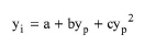
The user specifies the crystallization yield, yp, of the main soluble product component and identifies its crystallized form. The crystallization yields, yi, of all other components (i) that crystallize are specified as a function of the product crystallization yield by a second-degree polynomial equation:
|
|
The heat of crystallization and the heat of evaporation should be specified at the reference temperature of 25 °C. If evaporation is considered, it is assumed that it takes place prior to crystallization.
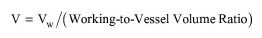
In Design Mode of calculation, the user specifies the residence time (tR) and the working to vessel volume ratio. The working (liquid) volume (Vw) and the vessel volume (V) are calculated using the following equations:
|
|
|
|
where F is the feed volumetric flowrate. If the calculated vessel volume exceeds its maximum possible value (specified through the Equipment tab), the program assumes multiple, identical units operating in parallel with a total vessel volume equal to the calculated.
In Rating Mode, the user specifies the vessel volume, the number of units, and either the residence time or the working to vessel volume ratio. When the residence time is specified, the program calculates the working to vessel volume ratio using the above equations and checks to make sure that the calculated value is between the minimum and maximum working to vessel volume ratio. When the working to vessel volume ratio is specified, the program calculates the residence time using the above equations.
If this unit operates in a batch plant, the feed flowrate F is calculated by dividing the volume of material that needs to be processed per cycle by the process time.
Equipment purchase cost is based on total vessel volume, agitation power and material of construction. It includes the cost of the vessel along with the agitator cost. If the vessel is checked as an ‘ASME Vessel’ (i.e., constructed according to standards published by the American Society of Mechanical Engineers) then it is assumed to withstand pressure to 35 psig and its purchase cost is penalized by 20% over the base vessel cost. If the operating pressure of the vessel is set to a pressure higher than 3 atm, then the vessel’s purchase cost is penalized by an 80% increase over the base cost.
See Vacuum Pump Auxiliary Equipment Calculations.
The interface of this operation has the following tabs:
● Oper. Cond’s, see Continuous Crystallization: Oper. Conds Tab
● Volumes, see Continuous Vessel Operations (Design Mode): Volumes Tab and Continuous Vessel Operations (Rating Mode): Volumes Tab
● Evap. Data, see Continuous Crystallization: Evap. Data Tab
● Crystal. Data, see Continuous Crystallization: Crystal. Data Tab
● Labor, etc, see Operations Dialog: Labor etc. Tab
● Description, see Operations Dialog: Description Tab
● Batch Sheet, see Operations Dialog: Batch Sheet Tab
● Scheduling, see Operations Dialog: Scheduling Tab