eq. (A.309)
This unit operation model simulates crystallization under continuous flow by lowering the temperature of the solution. Cooling crystallization is a widely used technique in chemical and pharmaceutical industries for the purification and formation of solid crystals from a solution. The basic principle involves reducing the temperature of a saturated solution to lower the solubility of the solute, causing it to crystallize out of the solution.
● Continuous Cooling Crystallization Procedure
During crystallization, one or more components will be converted from their soluble forms into their crystallized forms. Initially, the user has to select whether one or multiply components that crystallize. This selection will be used to adjust the controls appearing in the Continuous Crystallization: Crystal. Data Tab.
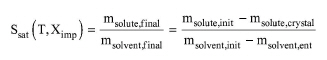
The mass balances for the crystallization design component can be based either on a user specified crystallization yield (yp) or the design component’s solubility curve. If the solubility curve is unknown, the user must specify both the design component yield and the crystallization temperature. In the opposite case, only one of these parameters needs to be specified and the other will be calculated by the program based on the equation below:
|
|
eq. (A.309) |
In the equation above, msolute, final and msolvent, final are the mass of solute and solvent after crystallization, respectively. msolute, init and msolvent, init are the initial amounts of solute and solvent, msolute, crystal is the mass of the solute that crystallizes and msolvent, ent is the mass of solvent that is entrapped in the crystals formed. Regarding the setup of solvent entrapment, the user is just required to define a single component as the co-crystallization agent. The amount entrapped is calculated by the program based on the molecular weights of the solute and crystal form components.
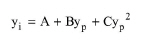
The crystallization yield for secondary crystal components (yi) is specified as a function of the crystallization yield of the design component (yp) using the following a second-degree polynomial equation:
|
|
There is additionally, the option to designate a co-crystallization agent for every crystallization that takes place. The co-crystallization agent is considered to be entrapped in the crystals formed according to the mass (or mole) ratio specified.
Energy Balances
A heat of crystallization should be specified for every component that crystallizes. Notice that the heat of crystallization should be negative to denote that the crystallization is exothermic (which is usually the case). SuperPro will calculate the cooling duty and the heat transfer agent flowrate required to maintain the crystallization temperature (either set by the user or calculated).
In Design Mode of calculation, the user specifies the residence time (tR) and the working to vessel volume ratio. The working (liquid) volume (Vw) and the vessel volume (V) are calculated using the following equations:
|
|
|
|
where F is the feed volumetric flowrate. If the calculated vessel volume exceeds its maximum possible value (specified through the Equipment tab), the program assumes multiple, identical units operating in parallel with a total vessel volume equal to the calculated.
In Rating Mode, the user specifies the vessel volume, the number of units, and either the residence time or the working to vessel volume ratio. When the residence time is specified, the program calculates the working to vessel volume ratio using the above equations and checks to make sure that the calculated value is between the minimum and maximum working to vessel volume ratio. When the working to vessel volume ratio is specified, the program calculates the residence time using the above equations.
If this unit operates in a batch plant, the feed flowrate F is calculated by dividing the volume of material that needs to be processed per cycle by the process time.
Equipment purchase cost is based on total crystallizer volume, agitation power and material of construction. It includes the cost of the vessel along with the agitator cost. If the equipment is checked as an ‘ASME Vessel’ (i.e., constructed according to standards published by the American Society of Mechanical Engineers) then it is assumed to withstand pressure to 35 psig and its purchase cost is penalized by 20% over the base vessel cost. Finally, the purchase cost is increased by 80% if the design pressure is higher than 3 atm.
See Vacuum Pump Auxiliary Equipment Calculations.
The interface of this operation has the following tabs:
● Oper. Cond’s, see Continuous Cooling Crystallization: Oper. Conds Tab
● Solubility Data, see Continuous Cooling Crystallization: Solubility Data Dialog
● Crystal. Data, see Continuous Crystallization: Crystal. Data Tab
● Volumes, see Continuous Vessel Operations (Design Mode): Volumes Tab and Continuous Vessel Operations (Rating Mode): Volumes Tab
● Vent/Emissions, see Vessel Operations: Vent/Emissions Tab
● Labor, etc, see Operations Dialog: Labor etc. Tab
● Description, see Operations Dialog: Description Tab
● Batch Sheet, see Operations Dialog: Batch Sheet Tab
● Scheduling, see Operations Dialog: Scheduling Tab