This operation simulates the separation of dense liquid/solid particles from liquid in a suspension using a hydrocyclone. Hydrocyclones can be used for solid-liquid and liquid-liquid separation and solids classification for particles with size in the range of 4 to 500 µm.
● Centrifugation in a Hydrocyclone Procedure
A pure component can be set to be removed by checking the corresponding “Removed ?” option on the Operation Data dialog. If a pure component is set to be removed, then the corresponding liquid/solid phase amount in the feed stream is assumed to consist of high density liquid/solid particles, which will end up mainly in the underflow. These high density liquid/solid particles are denoted as “particles” in the rest of this text as well as on the Operation Data dialog.
On the other hand, if a pure component is not set to be removed (i.e., the corresponding “Removed ?” option is not checked on the Operation Data dialog), then the corresponding liquid/solid phase material of the feed stream is assumed to consist of low density liquid/solid particles, which will exit mainly through the overflow. These low density liquid/solid particles are denoted as “liquid” in the rest of this text as well as on the Operation Data dialog.
If a pure component also appears in the gas phase in the feed stream, then the corresponding gaseous amount is considered inert gas and it is ignored in subsequent material balance calculations (it is neither included in the “particle” phase of the feed stream nor in its “liquid” phase).
For each pure component that is set to be removed, a percentage of the corresponding particle amount in the feed stream equal to the corresponding Removal % shown on the Operation Data dialog will end up in the underflow and the rest will end up in the overflow. If the equipment’s design/sizing option is “Based On Throughput”, or if it is “Based On Body Diameter” and the operation’s particle removal option is “Set By User”, then the user must specify the particle Removal % for each pure component that is set to be removed. On the other hand, if the equipment’s design/sizing option is “Based On Body Diameter” and the operation’s particle removal option is set to “Calculated”, then the particle Removal % for each pure component that is set to be removed will be set equal to the Overall Removal Efficiency that is calculated by the program.
For each pure component that is not set to be removed, a percentage of the corresponding liquid amount in the feed stream equal to the “Underflow To Throughput Liquid Flow Ratio” (described later) will end up in the underflow stream and the rest will end up in the overflow stream.
As explained earlier, any material that appears in the gas phase of the feed stream is ignored in material balance calculations regardless of whether the corresponding pure component is set to be removed or not. This material is simply sent to the overflow stream.
This is the total particle separation (or recovery) efficiency, which is defined as the ratio of the total particle mass flow rate of the underflow to the total particle mass flow rate of the feed.
If the equipment design/sizing is “Based On Throughput”, or if it is “Based On Body Diameter” and the operation’s particle removal option is “Set By User”, then the user can specify the particle Removal % for each pure component that is set to be removed. Based on this, the total particle mass flow rate of the underflow is determined by doing the material balances as described above.
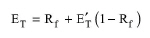
If the equipment design/sizing is “Based On Body Diameter” and the operation’s particle removal option is set to “Calculated”, then the program first calculates the reduced overall efficiency and underflow to throughput flow ratio values (described later), and then it calculates the overall efficiency as:
|
|
where:
● ET is the overall removal efficiency
● E’T is the reduced overall efficiency
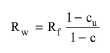
● Rf is the underflow to throughput flow ratio
The particle concentration in the feed stream is defined as the ratio of particle volume to total liquid/solid volume for the feed stream (expressed as volume %).
The particle concentration in the underflow is defined as the ratio of particle volume to total liquid/solid volume for the underflow (expressed as volume %).
If the equipment is in rating mode, and the equipment design/sizing is based on body diameter and dimensionless analysis, then the particle concentration in the underflow is calculated based on eq. (A.145). In all other cases, it must be set by the user.
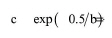
The particle concentration in the overflow is defined as the ratio of particle volume to total liquid/solid volume for the overflow (expressed as volume %). It can also be calculated as c(1.0-ET)/(1.0 - Rf), where c is the particle concentration by volume in the feed.
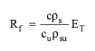
The Underflow To Throughput Flow Ratio is defined as the ratio of the volumetric flow rate of the liquid/solid phase of the underflow stream to the volumetric flow rate of the liquid/solid phase of the feed stream. It can be calculated as:
|
|
where:
● c is the Particle Concentration in Feed.
● cu is the Particle Concentration in Underflow.
● ρs is the particle density in the feed.
● ρsu is the particle density in the underflow.
The Underflow To Throughput Flow Ratio is calculated based on the above equation for all cases except one: if the equipment is in rating mode, and the equipment design/sizing is based on body diameter and dImensionless analysis, then the Underflow To Throughput Flow Ratio is calculated by solving the equations of the dimensionless group model (described later).
The Underflow To Throughput Liquid Flow Ratio is defined as the ratio of the volumetric flow rate of liquid in the underflow to the volumetric flow rate of liquid in the feed. It is calculated as:
|
|
eq. (A.146) |
where:
● Rw is the underflow to throughput liquid flow ratio.
Note that this variable is calculated internally and its value is not shown on the operation’s data dialog.
If the equipment design/sizing is Based On Throughput, then, in design mode, the user specifies the Max Throughput and the program calculates the Number of Units and the Rated Throughput based on the total volumetric liquid/solid throughput demand for the entire operation. If the total volumetric liquid/solid throughput demand exceeds the specification for the Max Throughput, then the program assumes multiple number of identical units that are operated in parallel, each having a Rated Throughput equal to the ratio of the total volumetric liquid/solid throughput demand to the total number of units. In rating mode, the Rated Throughput and the Number of Units are set by the user and the program simply carries out the material balances.
If the equipment Design/Sizing is Based On Body Diameter and Inlet Velocity, then, in Design mode, the user specifies the Max Body Diameter and additional information regarding the selected geometry. The program calculates the Number of Units and the Body Diameter based on the total volumetric liquid/solid throughput demand of the operation and on the specified inlet velocity of the feed slurry. If the total volumetric liquid/solid throughput demand exceeds the maximum rated throughput (which is calculated based on the Max Body Diameter, the ratio of Inlet Diameter to Body Diameter, and the Inlet Velocity), then the program assumes multiple number of identical units that are operated in parallel, each having a Rated Throughput equal to the ratio of the total volumetric liquid/solid throughput demand to the total number of units. In Rating Mode, the Body Diameter and the Number of Units are set by the user and the program calculates the Rated Throughput as the ratio of the total volumetric liquid/solid throughput demand to the Number of Units. Then, based on the ratio of Inlet Diameter to Body Diameter it calculates the inlet area, and based on the inlet area and the Rated Throughput it calculates the Inlet Velocity.
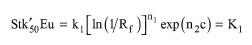
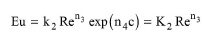
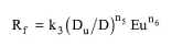
If the equipment Design/Sizing is Based On Body Diameter and Dimensionless Analysis, then the equipment sizing is based on the following dimensionless group model equations by Svarovsky:
|
|
eq. (A.147) |
|
|
eq. (A.148) |
|
|
eq. (A.149) |
where:
● Stk’50 is the reduced Stokes number
● Eu is the Euler number
● Re is the Reynolds number
● k1, k2, k3, n1, n2, n3, n4, n5 and n6 are dimensionless scale-up parameters that mainly depend on the cyclone geometry
● c is the particle volume fraction in the feed
● Rf is the underflow to throughput volumetric flow ratio
● D is the body diameter of the cyclone
● Du is the underflow diameter of the cyclone
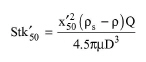
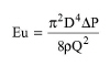
The reduced Stokes number, the Euler number and the Reynolds number are defined as:
|
|
eq. (A.150) |
|
|
eq. (A.151) |
|
|
eq. (A.152) |
where:
● x’50 is the reduced 50% cut size
● ρ is the liquid density
● ρs is the solids density in the feed
● Q is the operating volumetric throughput per unit
● μ is the liquid viscosity
● ΔP is the pressure drop
Note that the above model is suitable for low feed particle concentrations (up to 10% by volume).
In Design Mode, the user specifies the equipment’s Max Body Diameter and Max Pressure Drop, as well as all geometric proportions related to body diameter except the ratio of underflow diameter to body diameter (which is an operating variable). At the operation level, the user also specifies the Reduced 50% Cut Size and the Particle Concentration in Underflow. By solving the above equations simultaneously, the program calculates the Number of Units, the Body Diameter, the ratio of Underflow Diameter to Body Diameter and the Pressure Drop, so that the Body Diameter does not exceed the Max Body Diameter and the Pressure Drop does not exceed the Max Pressure Drop. Then, the program calculates all cyclone dimensions based on their respective geometric proportions relative to body diameter.
In Rating Mode, the user specifies at the equipment level the Number of Units and the Body Diameter, as well as all geometric proportions related to body diameter (including the ratio of underflow diameter to body diameter). At the operation level, the user also specifies the Reduced 50% Cut Size. By solving the above equations simultaneously, the program calculates the Pressure Drop and the Underflow To Throughput Flow Ratio. Then, based on the latter, it calculates the Particle Concentration In Underflow. Also, the program calculates all cyclone dimensions based on their respective geometric proportions relative to body diameter.
The operating throughput (per unit) is calculated as:
|
|
eq. (A.153) |
Where:
● Q is the operating throughput per unit
● Qtot is the total operating throughput over all units
● N is the number of units
The pressure drop is set by user if the equipment Design/Sizing is Based On Throughput and if the equipment Design/Sizing is Based On Body Diameter and Inlet Velocity. If the equipment Design/Sizing Based On Body Diameter and Dimensionless Analysis, then the pressure drop is calculated by the program based on the dimensionless group model equations described above.
The total power consumption by this operation (for pumping, etc.) is calculated as Qtot ΔP / η, where η is the total power efficiency (the ratio of ideal to actual power consumption for pumping, etc.). The value of the total power efficiency is 100% by default and can be changed by the user.
The pressures of the underflow and overflow are assumed equal to the ambient pressure (i.e., the pressure drop is neglected for simplicity).
The Reduced Overall Efficiency is available only if the equipment Design/Sizing is Based On Body Diameter and the Particle Removal is Calculated. It is a “corrected” efficiency that illustrates only the net effect of separation due to centrifugal forces and not the effect of separation due to the splitting of the total flow (or “dead flux”) that carries liquid and suspended fine particles into the underflow. It is defined based on eq. (A.144). If the Particle Removal is Calculated, then the Reduced Overall Efficiency is calculated as:
|
|
eq. (A.154) |
where:
● G’ is the reduced grade efficiency curve
● F is the cumulative mass % undersize particle size distribution of the feed
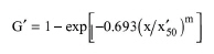
The reduced grade efficiency is available only if the equipment Design/Sizing is Based On Body Diameter and the Particle Removal is Calculated. It is defined as the reduced separation efficiency corresponding to a particular particle size. Here, it is calculated based on the proposed modification of the Rosin-Rammler equation by Plitt:
|
|
eq. (A.155) |
where:
● x is the particle size
● x’50 is the reduced 50% particle size (cut size)
● m is a parameter that depends on the cyclone geometry
● G’ is the reduced grade efficiency.
The Reduced 50% Cut Size is available only if the equipment Design/Sizing is Based On Body Diameter and Inlet Velocity, and the Particle Removal is Calculated, or if the equipment Design/Sizing is Based On Body Diameter and Dimensionless Analysis. It is defined as the particle size for which the reduced grade efficiency is 50%. Therefore, it can be calculated as the root of function f’(x) = G’(x) - 0.5. Here, it is always set by the user (when available).
The 50% Cut Size is available only if the equipment Design/Sizing is Based On Body Diameter and the Particle Removal is Calculated. It is defined as the particle size for which the grade efficiency is 50%. Therefore, it can be calculated as the root of function f(x) = G(x) - 0.5, where G is the grade efficiency. The grade efficiency can be calculated based on the reduced grade efficiency by an equation similar to eq. (A.144), in which E is substituted by G.
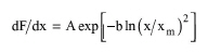
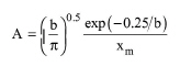
A cumulative mass % undersize particle size distribution is used if the equipment Design/Sizing is Based On Body Diameter and the Particle Removal is Calculated. The cumulative mass % undersize is assumed to follow a lognormal particle size distribution:
|
|
eq. (A.156) |
where:
|
|
eq. (A.157) |
|
|
eq. (A.158) |
|
|
eq. (A.159) |
|
|
eq. (A.160) |
and:
● xg is the geometric mean (or median) of the lognormal particle size distribution of the feed
● sg is the geometric standard deviation of the lognormal particle size distribution of the feed
If the particle size distribution model parameters are Set by User, then the user must specify the values of xg and sg. If, on the other hand, these parameters are Calculated Based on PSD Data, then these parameters will be calculated by the program by fitting a lognormal particle size distribution to the actual feed particle size distribution data specified by the user (as a set of particle size - cumulative mass % undersize data points).
1. Svarovsky L., “Solid-Liquid Separation”, 4th Ed, Butterworth-Heinemann, 2000.
2. Coelho M.A.Z. and Medronho R.A., “A model for performance prediction of hydrocyclones”, Chemical Engineering Journal, vol. 84, pp. 7-14, 2001.
If the equipment design/sizing is based on throughput, the interface of this operation has the following tabs:
● Oper. Cond’s, see Centrifugation in a Hydrocyclone: Oper. Conds Tab (Based on Throughput)
● Mat. Balance, see Centrifugation in a Hydrocyclone: Mat. Balance Tab (Based On Throughput)
● Labor, etc, see Operations Dialog: Labor etc. Tab
● Description, see Operations Dialog: Description Tab
● Batch Sheet, see Operations Dialog: Batch Sheet Tab
● Scheduling, see Operations Dialog: Scheduling Tab
If the equipment design/sizing is based on body diameter and inlet velocity, the interface of this operation has the following tabs:
● Oper. Cond’s, see Centrifugation in a Hydrocyclone: Oper. Conds Tab (Based on B. Diam. & Inlet Vel.)
● Mat. Balance, see Centrifugation in a Hydrocyclone: Mat. Balance Tab (Based On Body Diameter)
● PSD, see Centrifugation in a Hydrocyclone: PSD Tab
● Labor, etc, see Operations Dialog: Labor etc. Tab
● Description, see Operations Dialog: Description Tab
● Batch Sheet, see Operations Dialog: Batch Sheet Tab
● Scheduling, see Operations Dialog: Scheduling Tab
If the equipment design/sizing is based on body diameter and dimensionless analysis, the interface of this operation has the following tabs:
● Oper. Cond’s, see Centrifugation in a Hydrocyclone: Oper. Conds Tab (Based on B. Diam. & Dim. Anal.)
● Mat. Balance, see Centrifugation in a Hydrocyclone: Mat. Balance Tab (Based On Body Diameter)
● PSD, see Centrifugation in a Hydrocyclone: PSD Tab
● Labor, etc, see Operations Dialog: Labor etc. Tab
● Description, see Operations Dialog: Description Tab
● Batch Sheet, see Operations Dialog: Batch Sheet Tab
● Scheduling, see Operations Dialog: Scheduling Tab