This tab appears on the interface dialog of the Hydrocycloning operation (see Centrifugation in a Hydrocyclone) when the option to size the equipment based on throughput is selected through the Equipment tab of the Hydrocyclone that hosts this operation (see Hydrocyclone: Equipment Tab).
The following table shows a brief description of the variables appearing in this tab. The table also displays their default values and their generally acceptable range:
|
Variable |
Default Value |
Range |
|
|
||
|
○ Removed ? |
No |
Yes/No |
|
○ Removal % |
0.0 |
0 – 100 |
|
● Overall Removal Efficiency (%) |
0.0 |
Positive |
|
● Particle Concentration in Feed (% v/v) |
0.0 |
0 – 100 |
|
◙ Particle Concentration in Underflow (% v/v) |
20.0 |
0 – 100 |
|
◙ Particle Mass % in Underflow |
0.0 |
0 – 100 |
|
● Particle Concentration in Overflow (% v/v) |
0.0 |
0 – 100 |
|
● Underflow/Throughput Flow Ratio (v/v) |
0.0 |
Positive |
Symbol Key: ○ User-specified value (always input); ● Calculated value (always output); ◙ Sometimes input, sometimes output
The following list describes the available specification choices in this tab; for more details on how these are implemented, see Centrifugation in a Hydrocyclone: Modeling Calculations.
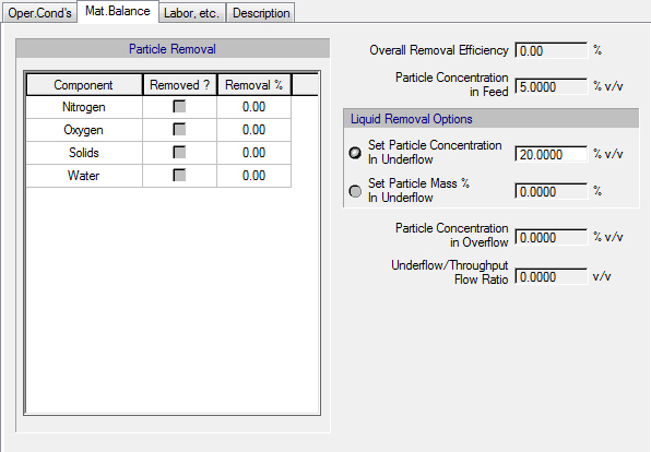
•Particle Removal Data...
Specify which components consist of high density liquid/solid particles (which are expected to exit mainly through the underflow) by checking the ‘Removed ?’ option next to each component. For each component for which the “Removed ?” option is checked, you also need to specify the corresponding Removal %.
•Liquid Removal Options...
Two options are available for specifying the amount of liquid (i.e., liquid/solid content of pure components that are not set to be removed) that is recovered in the underflow. You can either specify the Particle Concentration In Underflow (expressed as volume %) or the Particle Mass % In Underflow.