The i/o simulation dialog of an operation is made up from several tabs. Each tab presents a group of variables. Some variables are required to be set by the user (inputs) and others are
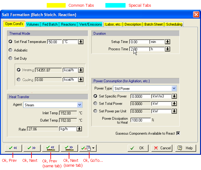
A typical input/output (i/o) simulation dialog for an operation.
calculated by the simulation engine (outputs). Sometimes a variable may be considered an input or an output depending on other operation-related or procedure-related settings (e.g. operating mode), or even equipment-related settings (e.g. sizing options). Most input variables come preset to some reasonable default values. A typical i/o simulation dialog is shown below (for the stoichiometric reaction operation)
As a shortcut to visiting another operation’s i/o simulation dialog in the same unit procedure queue, this dialog offers (besides the regular OK, Cancel, Help buttons) another set of buttons that allow you to accept the changes in this dialog and automatically open the i/o simulation dialog of another operation (next or previous in the sequence order). The first two buttons open the next (or previous) operation dialog and show the first tab (typically the ‘Oper.Cond’s’ tab) whereas the next two buttons open the next (or previous) operation’s i/o simulation dialog at the same tab as the one being viewed currently (if it exists). Finally, the fifth button allows you to jump to another operation’s dialog (not necessarily the next or previous in the sequence order). Note that moving your cursor over the buttons of the dialog will present a tooltip reminder of their functionality
|
|
Even though the ‘Oper. Cond’s’ tab is common to all operations, the contents of the tab (i.e. the variables that belong in this group) can vary significantly from operation to operation. The other four common tabs (‘Labor etc’., ‘Description’, ‘Batch Sheet’ and ‘Scheduling’) when they appear they are exactly the same in all operations. |
.
If you need to get some information related to the meaning or legal range of values for any of the parameters appearing on any of the dialog’s tabs, just click on Help (or hit F1 on your keyboard) and you will be presented with a topic that provides you with information related to the specific tab that you are viewing. Also, from the same help topic, you will find links that will lead to a detailed description of the modeling equations behind the specific operation.
This tab focuses on covering the following three issues (common to all operations):
1. Labor Demand: There can be several types of labor that can be associated with the carrying out of an operation: plain operator type, supervisory labor, quality-control labor, etc. SuperPro will track the requirements of each labor type provided the user specifies for each operation what type of labor(s) is needed and at what rate (labor-hours per operation-hour or per cycle). If the type of labor that you wish to associate with an operation is not available already you can introduce new types (see Adding or Deleting a Labor Type).
2. Auxiliary Equipment: There are four pre-built auxiliary equipment types (CIP skid, SIP panel, vacuum pump and transfer panel) but users could create more custom-types of their own (e.g. blowers, in-line filters, etc.) see Auxiliary Equipment. From this property page you can engage any auxiliary equipment with that operation. The engagement is not in any way helped or impeded by the performance of the operation. SuperPro will simply track engagements of the assigned auxiliary equipment and identify sharing violations. Also, any consumables associated with the operation of the assigned auxiliary equipment will add to the total operating cost.
3. Auxiliary Utilities (heating, cooling or power) demand: Oftentimes, it may be required to dedicate extra amounts of utilities in the form of heating or cooling or power for reasons that are unaccounted by the simulation model of the operation. For each utility category you can specify the type and rate of consumption and then the calculated rates (and amounts) will be tacked on to the rates calculated by the model (if any). If the type of utility you need to assign is not available, you can introduce your own (see Adding or Deleting a Heat Transfer Agent and Adding or Deleting a Power Type).
4. Size (or Throughput) Utilization Factor: This number reflects the extent that the host equipment’s capacity (or throughput) is being utilized by the current operation. For example, for a charge operation that carries in 1,000L in a 10,000L vessel, the utilization factor is 10%. For operations that are hosted by equipment resources whose ‘size’ is measured by a throughput variable and not a capacity variable (e.g. a homogenizer) this ratio will be the effective throughput of the operation over the rated throughput of the host equipment. This measure is used in the throughput analysis calculations that estimate the throughput potential of an existing facility as well as pinpoint bottlenecks when attempting to expand the production level (see Potential Maximum Throughput Size).
The property page displaying the above set of variables for each operation is always the Operations Dialog: Labor etc. Tab.
This tab addresses two issues (common to all operations):
1. Verbal Description of the Operation: There are circumstances when SuperPro needs to verbally describe the events occurring in the process. For example, when we display the operation Gantt chart we can display right next to the activity bars a text description of what each bar represents (see The Operations Gantt Chart (OGC)). Also, when shift+clicking over a unit procedure, a tooltip window appears that displays a brief overview of the activities included in that procedure (see Quick View of the Activities under a Unit Procedure). The description settings of an operation dictate how SuperPro will put together a textual description that will use to represent this operation. Most operations have a short and a long textual description of themselves. Note that the description may include actual values of operating parameters (e.g. amounts charged, reaction conditions, etc.). The user may also choose to overwrite the pre-existing templates for the operation and provide his/her own description. Unfortunately that description will be supplied ‘as-is’ without employing any operating variables.
2. Comments: If you wish to associate any comments that may be reminders for you or another viewer of the process, this is the place to add them. For example, it may be of importance to note here sources for the values of settings chosen in the operation, or any other assumptions or simplifications made when approximating the real process event(s) with the operation chosen.
The property page displaying the above set of variables for each operation is always the Operations Dialog: Description Tab.
This tab addresses how SuperPro Designer will describe this operation when generating the batch sheet for the process. The ‘Batch Sheet’ is a very long document that describes in great detail the actions involved in the execution of the recipe. Typically, each operation is described based on a template (or form) that is operation-type specific. SuperPro Designer instantiates each operation’s type form for a given operation, fills in the template with the operational values required and adds the resulting description in a master document whose structure is also dictated by a master template. For more details on the Batch Sheet, see Batch Sheet Generation.
You may elect not to include a given operation in the batch sheet, or you may chose to utilize a textual description that is simply the description text of the operation. All the choices related to this group of variables are presented in the Operations Dialog: Batch Sheet Tab.
This group of variables are always presented for viewing and/or editing on theOperations Dialog: Scheduling Tab and are used to capture the following attributes:
1. The start time of the operation
SuperPro Designer calculates the start time of an operation using two settings:
(a) A reference event and (b) a time shift (positive or negative) from that event.
The reference event can be one of the following:
(a) The beginning of the batch
(b) The start time or end time of another operation in the same or another procedure.
2. The duration of the operation
It is assumed that the entire duration of an operation is made up from three parts:
(a) The setup time
(b) The process time, and
(c) The turnaround time
Users may elect to specify each portion of the entire duration separately or lump them together in one or two values alone.
The process time of an operation can often be (optionally) calculated based on some performance variable of the operation: for example, a charge operation may compute its process time based on a user-specified charge rate. In some (rare) operations the process time is always calculated (e.g. ‘Column Load’ in a chromatography column). When the process time can be calculated based on some other attribute of the operation, it is also displayed in the Oper. Cond’s tab.
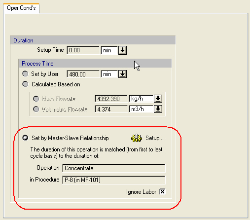
The process time can be dictated from a master-slave relationship.
As another alternative to calculate the duration of an operation, a user may elect to match the duration of one operation (master) to the duration of another (slave). This option is available to several operations and, when available, it is set from the Oper. Cond’s tab of the operation (The process time can be dictated from a master-slave relationship.). After selecting to set the process time by a master operation, clicking on the ‘Setup’ button will bring up the The Master-Slave Relationship Dialog that will allow the user to select the master operation.
