This operation is used to simulate the compression of air in an air compressor, the combustion of gaseous fuel (e.g., natural gas) in the presence of the compressed air in a combustion chamber, the expansion of the combustion gas in an expansion turbine, and the conversion of mechanical energy into electricity in an electric generator.
● Power Generation in a Gas Turbine-Generator Procedure
Fuel and air are fed into the hosting equipment continuously through the designated input ports for the fuel and air streams, respectively. The fuel stream is used to carry combustible gaseous fuels (e.g., natural gas, biogas, etc.) and the air stream is used to carry the oxygen for combustion. The exhaust gas is transferred out continuously using the available output port.
The flow of the air stream is always adjusted to match the specified percent excess oxygen of the air-fuel mixture or the specified air-fuel ratio. If the percent excess oxygen is specified, the mass flow rate of the air stream is calculated as:
|
|
where mair is the mass flow rate of the air stream, mO2,air is the stoichiometric mass flow rate of oxygen in the air stream, wO2,air is the mass fraction of oxygen in the air stream, mfuel is the mass flow rate of the fuel stream, wr,O2 is the theoretical mass of oxygen required for complete combustion of the fuel stream per unit mass of fuel stream, and wO2,fuel is the available mass of oxygen in the fuel stream (which is the sum of total fuel elemental oxygen and fuel stream oxygen) per unit mass of fuel stream. The calculation of wr,O2 and mO2,air is described in the section that describes the mass balances of combustion reactions.
The relative humidity of air is calculated by dividing the partial pressure of water vapor in the air stream by the saturation pressure of water vapor at the specified air stream temperature. The partial pressure of water vapor in the air stream is calculated by multiplying the pressure of the air stream by the mol fraction of water vapor in the air stream. The saturation pressure of water vapor at the specified air stream temperature is calculated from the saturated vapor pressure (Antoine) correlation for the pure component which is associated with water through the Fuel-Air Combustion: Components Tab.
Two different models are available for this operation:
● Detailed model (default): It includes models of air compression and gas expansion. The user must specify the pressure ratio and efficiency of the compressor, as well as the turbine efficiency.
● Simplified model: It does not use any models of air compression or gas expansion. The user simply specifies the thermal efficiency of the gas turbine (i.e., ratio of net power output to fuel heat input based on LHV), and based on this, the program calculates the net power output of the turbine. Then, the exhaust gas enthalpy (and temperature) is simply calculated based on the following overall energy balance: fuel enthalpy + air enthalpy + reaction heat = exhaust gas enthalpy + net power output.
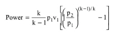
In the air compressor, the air is compressed to a pressure equal to the specified pressure ratio multiplied by the inlet pressure. To calculate the power requirement of the actual process, this model assumes an isentropic process and calculates first the power requirement for that process based on the following equation:
|
|
where:
● Power is the power requirement for an isentropic process (or isentropic power)
● k is the mean ratio of specific heats, Cp/Cv, where Cp is the specific heat capacity of gas at constant pressure and Cv is the specific heat of gas at constant volume,
● v1 is the volumetric throughput of gas at the inlet,
● p1 is the inlet pressure, and
● p2 is the outlet pressure.
To estimate the mean specific heat ratio, the program assumes an incompressible ideal gas and calculates the specific heat ratio as k=Cp/(Cp-R), where R is the universal gas constant. First, it calculates the specific heat ratio at the inlet, then it calculates the specific heat ratio at the outlet, and then it takes the average of the two.
The power requirement of the actual compression process is calculated by dividing the isentropic compression power by the specified isentropic compression efficiency.
To calculate the enthalpy (and temperature) at the outlet of the compressor, the program solves the following energy balance: compressor inlet enthalpy + compressor power = compressor outlet enthalpy.
The model considers the complete combustion of combustible fuel elements C, H and S into carbon dioxide, water vapor and sulfur dioxide, respectively, in the presence of stoichiometric or excess oxygen. For each pure component of the fuel stream that is identified by the user as a combustible fuel, its elemental C, H, O, N and S composition must be specified (see Fuel-Air Combustion: Fuel Tab). If the fuel contains additional elements, then these may be added to the composition of elemental N. Any molecule present in the combustion gas (i.e., carbon dioxide, water, sulfur dioxide, oxygen) must be associated explicitly with a registered pure component (see Fuel-Air Combustion: Components Tab).
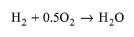
The elemental oxygen contained in the fuel is assumed to participate in combustion reactions with C, H and S. The elemental nitrogen contained in the fuel is taken to appear as gaseous nitrogen in the combustion products. The reaction of nitrogen contained in the air with oxygen and hydrocarbons is not considered. Only the following combustion reactions are considered:
|
|
|
|
|
|
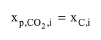
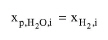
From the stoichiometry of the above reactions, the moles of combustion gases CO2, H2O and SO2 produced per mole of fuel component i from the complete combustion of that component are calculated as:
|
|
|
|
|
|
where xC,i, xH2,i and xS,i are the respective moles of elemental carbon, elemental hydrogen and elemental sulfur per mole of fuel component i. The total mass flow rate of combustion gas j (j=CO2, H2O, or SO2) produced by complete combustion of all combustible fuel components can be calculated as:
|
|
where Mj is the molecular weight of combustion gas j, ni is the mole flow of fuel component i, Mi is the molecular weight of fuel component i, and wi is the mass fraction of fuel component i.
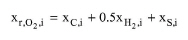
The theoretical moles of oxygen required for the complete combustion of fuel component i per mole of that fuel component can be calculated as:
|
|
Then, the total mass flow rate of theoretical oxygen required for the complete combustion of all fuel components can be calculated as:
|
|
where wr,O2 is the theoretical mass of oxygen required for complete combustion of the fuel per unit mass of fuel. The stoichiometric air-fuel ratio displayed on the interface of this operation can then be calculated by dividing mr,O2 by the mass flow rate of the fuel stream.
From the stoichiometry of the combustion reactions, the molar heat of combustion of each fuel component is calculated as:
|
|
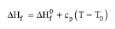
where ΔHf is the molar enthalpy of formation of each molecule. This is calculated as:
|
|
where:
● ΔH0f is the standard enthalpy of formation of the molecule,
● Cp is the mean specific heat capacity of the molecule,
● T0 is the temperature at which the standard enthalpies of formation are given (25 oC), and
● T is the reference temperature used for enthalpy calculations by the program.
The lower heating value (LHV) of each fuel component corresponds to the negative value of the standard enthalpy of combustion (LHVi=-ΔΗoc,i). This can be calculated from eq. (A.398), if ΔHf is substituted by ΔHof for all molecules.
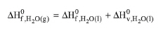
The standard enthalpies of formation of fuel components and of pure component associated with combustion products (CO2, H2O, SO2, and O2) are taken from the program’s pure component database. The standard enthalpy of formation of the “Water” component included in the Designer database (-285.83 kJ/mol) corresponds to liquid water. In a similar manner, the standard enthalpy of formation of the pure component that is associated with H2O is assumed to correspond to liquid water. This is converted into standard enthalpy of formation of water vapor, as follows:
|
|
where ΔH0v is the latent heat of vaporization of water at 25 oC (which is assumed equal to 44 kJ/mol).
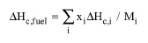
The total heat of combustion of the fuel stream expressed in units of energy per unit mass of fuel stream is calculated as:
|
|
where xi is the mass fraction of fuel component i in the fuel stream.
The total heat in the combustion chamber expressed in units of energy per unit mass of fuel stream can be calculated as:
|
|
where ΔHfuel is the specific enthalpy of the fuel stream and ΔHair is the specific enthalpy of the air stream.
The energy balance in the combustion chamber is this: mfuelΔHtot = mgasΔΗgas + Qloss, where mgas and ΔΗgas are the mass flow rate and specific enthalpy, respectively, of the combustion gas at the outlet of the combustion chamber, and Qloss is the heat lost to the surroundings. It is assumed that Qloss is zero. The above energy balance is first solved for ΔΗgas and then the outlet temperature of combustion gas is calculated based on ΔΗgas and the outlet pressure of the combustion chamber. The latter is assumed equal to the inlet pressure into the combustion chamber. The inlet pressure into the combustion chamber is assumed equal to the outlet pressure of the air compressor.
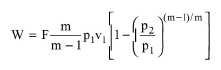
The theoretical power output of isentropic expansion of the combustion gas can be calculated as:
|
|
where F is the mass flow rate of gas, m is the mean specific heat ratio of gas, v1 is the specific volume of gas at turbine inlet, p1 is the pressure of gas at turbine inlet, and p2 is the pressure of gas at the turbine outlet. The latter is assumed equal to the ambient pressure.
The mean specific heat ratio of combustion gas is estimated similarly to that of air (see compression section).
The power output of the actual expansion process is calculated by multiplying the isentropic expansion power by the specified isentropic expansion efficiency.
To calculate the enthalpy (and temperature) at the outlet of the turbine, the program solves the following energy balance: turbine inlet enthalpy = turbine outlet enthalpy + turbine power.
In a gas turbine, the expansion turbine supplies the power required to drive the compressor. The net mechanical power output of the expansion turbine can be calculated by subtracting the compressor power from the turbine power.
The electric power produced by the electric generator that is coupled to the expansion turbine can be calculated by dividing the net mechanical power output of the expansion turbine by the specified generator efficiency.
The thermal efficiency of the gas turbine is defined as the ratio of the net power output of the gas turbine to the LHV-based thermal energy input of the fuel. Similarly, the electrical efficiency of the gas turbine is defined as the ratio of the electrical power output of the gas turbine to the LHV-based thermal energy input of the fuel. The LHV-based thermal energy input of the fuel can be calculated by first multiplying the mass flow rate of each fuel component by its LHV (which is in units of energy per unit mass of fuel) and then summing up the products of multiplication for all fuel components.
In Design mode, the user specifies the maximum (electric) power output of the gas turbine. If the operating power exceeds the maximum power, the program assumes multiple units operating in parallel with a total power equal to the calculated power.
If the equipment size option is in Rating Mode, the user specifies the rated (electric) power and the number of units. If the calculated power per unit exceeds the rated power, a warning is displayed advising the user to increase the rated power or the number of units.
1. Niessen, W. R., Combustion and Incineration Processes, Third Edition, Marcel Dekker, Inc., 2002.
2. Biomass Combined Heat and Power Catalog of Technologies, v1.1, EPA CHP Partnership, September 2007.
3. Boyce, M.P., Gas Turbine Engineering Handbook, 3rd edition, Elsevier, pp. 110-122, 2006.
4. Rutherford J., Heat and Power Applications of Advanced Biomass Gasifiers in New Zealand’s Wood Industry, Thesis Submitted in Fulfillment of the Requirements for the Degree of Master of Engineering in Chemical and Process Engineering, University of Canterbury, 2006.
The interface of this operation has the following tabs:
● Oper. Cond’s, see Power Generation in a Gas Turbine-Generator: Oper. Conds Tab
● Fuel, see Fuel-Air Combustion: Fuel Tab
● Components, see Fuel-Air Combustion: Components Tab
● Labor, etc, see Operations Dialog: Labor etc. Tab
● Description, see Operations Dialog: Description Tab
● Batch Sheet, see Operations Dialog: Batch Sheet Tab
● Scheduling, see Operations Dialog: Scheduling Tab