This operation models transport of gaseous materials using a centrifugal compressor.
● Compression in a Centrifugal Compressor Procedure
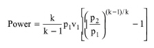
Compressors operate in pressure ranges and with compression ratios that often require external cooling to prevent damage to sensitive seals and metal surfaces. This physical situation falls between the isentropic and isothermal extremes and is called polytropic compression. To calculate the power requirement of the actual process, this model first assumes an isentropic process and calculates the power requirement for that process based on the following equation:
|
|
where:
● Power is the power requirement for an isentropic process (or isentropic power)
● k is the mean ratio of specific heats, Cp/Cv, where Cp is the mean specific heat capacity of gas at constant pressure and Cv is the mean specific heat of gas at constant volume,
● v1 is the volumetric throughput of gas at the inlet,
● p1 is the inlet pressure, and
● p2 is the outlet pressure.
Then, the power requirement for the actual process is calculated by dividing the isentropic power by the specified (isentropic) efficiency.
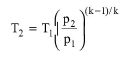
After calculating the power, the program solves the adiabatic energy balance around the compressor (inlet enthalpy + power = outlet enthalpy) to calculate the adiabatic outlet enthalpy. Then, it flashes the gas at the outlet pressure and adiabatic outlet enthalpy to calculate the adiabatic outlet temperature. This value is higher than the isentropic outlet temperature that can be estimated from the following equation:
|
|
where:
● T1 is the inlet temperature of gas, and
● T2 is the outlet temperature of gas for an isentropic process (or isentropic temperature).
Note that the mean specific heat capacity, k, is calculated as the average of the mean specific heat capacity values at the inlet and outlet, k1 and k2, respectively. Assuming incompressible ideal gas, k1 can be estimated as Cp1/(Cp1-R) and k2 can be estimated as Cp2/(Cp2-R). To estimate the mean k, an iterative algorithm is used. Using k1 as an initial guess for k, the algorithm first calculates the power from eq. (A.363). Then, it solves the adiabatic energy balance to calculate the outlet enthalpy and outlet temperature as described above, and from that, it calculates the outlet Cp. Then, k calculated as the average k1 and k1 and the calculations are repeated, until the difference between the old guess and the new guess is not significant.
In Design Mode, the user specifies the desired pressure change (which is equivalent to specifying the value of p2) and the above equations are used to calculate the power requirement and the outlet temperature. If the calculated power exceeds the maximum, the program assumes multiple units operating in parallel with a total power requirement equal to the calculated. It the calculated T2 exceeds the maximum exit temperature, the program calculates the required cooling duty to maintain an exit temperature equal to the maximum.
In Rating Mode, the user specifies the power supply and the number of units operating in parallel and the program calculates the pressure change.
1. Shultz, J.M. (1962). “The Polytropic Analysis of Centrifugal Compressors”, J. Eng. Power, Trans. Am. Soc. Mech. Eng., pp. 69-82 (January 1962).
2. Peters, M.S. and K.D. Timmerhaus, (1991). Plant Design and Economics for Chemical Engineers, 4th edition, McGraw-Hill, pp. 523-525.
The interface of this operation has the following tabs:
● Oper. Cond’s, see Compression: Oper. Conds Tab
● Labor, etc, see Operations Dialog: Labor etc. Tab
● Description, see Operations Dialog: Description Tab
● Batch Sheet, see Operations Dialog: Batch Sheet Tab
● Scheduling, see Operations Dialog: Scheduling Tab