Steam Generation
General Description
This operation is used to simulate the combustion of a fuel (e.g., methane, biomass, etc.) in the presence of air, and the subsequent transfer of heat from the flue gases to feedwater in order to convert the feedwater into steam, in a steam generator/boiler.
Unit Procedure Availability
● Steam Generation Procedure
Material Inputs / Outputs
Feedwater, fuel, and air are fed into the hosting equipment continuously through the dedicated input ports for feedwater, fuel, and air, respectively. The feedwater stream carries the water to be evaporated into steam. It may also contain minor quantities of impurities. The fuel stream is used to carry combustible fuels, such as hydrocarbons, and the air stream is used to carry the oxygen for combustion. The fuel stream may also contain sources of oxygen. Both streams may also contain inert components. These are gaseous or liquid/solid components that do not participate in combustion reactions. Upon combustion, the generated flue gases and any inert gaseous components of the fuel/air mixture are transferred to the dedicated output port that is connected to the flue gas stream. Any inert liquid/solid components of the fuel/air mixture are transferred to the dedicated output port that is connected to the ash stream. Finally, the feedwater exits as steam through the dedicated output port for steam.
Steam Generation: Modeling Calculations
This model simulates the complete combustion of fuel in the presence of air and the transfer of heat to feedwater in order to generate steam. Calculations are based on the elemental composition of fuel which is specified by the user, on the mass balances for the combustion reactions which are built into the model, and on the energy balances for the furnace part (where the combustion takes place) and the boiler part (where the transfer of heat from the flue gases to the feedwater takes place). The user may either set the flow of feedwater and let the program adjust the fuel flow to provide the necessary heat for steam generation, or set the fuel flow and let the program adjust the feedwater flow so that the heat transferred to feedwater matches the heat that is available for steam generation. The flow of air is always adjusted so that it matches the excess oxygen % specification by the user.
The user specifies the following parameters through the interface of this operation:
● The option to adjust either the feedwater stream or the fuel stream.
● The excess oxygen %.
● The temperatures of the ash and flue gas streams at the outlet.
● The option to either set the steam pressure or let the program set it equal to that of the feewater stream.
● The pressure of steam (if this is set by the user).
● The option to either set the temperature of steam or let the program set it equal to the calculated saturation temperature of the feewater stream at the specified pressure.
● The temperature of steam (if this is set by the user).
● The overall heat losses to the surroundings as a percentage of the total heat into the system (which is the sum of the sensible heats of the fuel and air stream and of the heat of combustion of the fuel with respect to the enthalpy reference conditions).
● The elemental (C, H, O, N, S), moisture, and ash composition of those pure components of the fuel stream that represent a combustible fuel.
● The pure components that are used to represent the molecules that are produced by the combustion of the fuel (CO2, H2O, O2, N2, SO2, and ash).
Based on the above parameters, the model calculates the following:
● The air flow requirement and air humidity (in kg/kg dry).
● The total heat in the system, which is defined as the sum of the sensible heats of the fuel and air streams and of the heat of reaction with respect to the enthalpy reference conditions (expressed in units of energy per unit mass of fuel).
● The available heat for steam generation, which is defined as the net heat transferred from flue gases to feedwater in the boiler (expressed in units of energy per mass of fuel).
● The temperature and pressure of generated steam (if they are not set by user).
● The required heat to convert feedwater into steam (expressed in units of energy per unit mass of steam).
● The fuel requirement (expressed as mass of fuel per unit mass of steam).
● The flow of the adjusted input stream (either feedwater or fuel).
● The flow and composition of the flue gas and ash output streams.
In addition, the model performs equipment sizing and calculates the operating throughput per unit. These are described below:
Composition of fuel stream
The model requires that the composition of combustible fuel components is specified (see Steam Generation: Elemental Composition Tab). The following elements are considered:
● Elements that are depleted upon combustion; these include carbon, hydrogen and sulfur. These elements do not need to be associated with a registered pure component.
● Elements and compounds that may be present in the final products; these include oxygen, nitrogen, water, and ash. The first three are automatically associated with a registered pure component. If the composition of a component includes ash, then the ash molecules must also be associated with a registered pure component (see Steam Generation: Components Tab)
If a combustible fuel component contains additional elements, their composition can be added to the composition of ash.
|

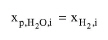
|
In the “Elemental Composition” tab, you only need to specify the composition of fuel components that contain combustible elements (carbon, or hydrogen, or sulfur). You do not need to specify the composition of pure components associated with the oxygen, water, nitrogen, carbon dioxide, sulfur dioxide and ash species through the “Components” tab.
|
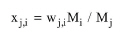
Based on the composition of fuel components, the mole fraction of each element/molecule contained in each fuel component is calculated as:
|
|
eq. (A.383)
|
where:
● wj,i is the mass fraction of the j-th element or molecule in the i-th component,
● Mi is the molecular weight and the i-th component, and
● Mj is the molecular weight of the j-th element.
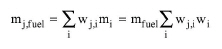
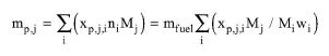
The total mass flow rate of each element/molecule contained in the fuel stream is calculated as:
|
|
eq. (A.384)
|
where:
● mi is the mass flow rate of the i-th component of the fuel stream,
● mfuel is the total mass flow rate of the fuel stream,
● wi is the mass fraction of the i-th component in the fuel stream.
If the fuel stream contains additional pure components whose composition doesn’t consist of C, H, N, O, S, moisture, and ash, then these pure components are assumed to be inert components, and their liquid/solid phase is transferred to the ash stream, and their gas phase is transferred to the flue gas stream.
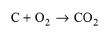
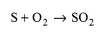
Mass balances of combustion reactions
The model considers the complete combustion of combustible fuel elements C, H2 and S into carbon dioxide, water vapor and sulfur dioxide, respectively, in the presence of stoichiometric or excess oxygen. Note that any molecule present in the flue gas (i.e., carbon dioxide, water, sulfur dioxide, oxygen) must be associated explicitly with a registered pure component through the Steam Generation: Components Tab. The corresponding combustion reactions are:
|
|
eq. (A.385)
|
|

|
eq. (A.386)
|
|
|
eq. (A.387)
|
From the stoichiometry of the above reactions, the moles of combustion gases produced per mole of fuel component from complete combustion of the fuel stream are calculated as:
|

|
eq. (A.388)
|
|
|
eq. (A.389)
|
|

|
eq. (A.390)
|
The total mass flow rate of each combustion gas produced from complete combustion of all combustible components in the fuel stream is calculated as:
|
|
eq. (A.391)
|
where ni is the mole flow of the i-th component of the fuel stream.
The moles of theoretical (stoichiometric) oxygen consumed per mole of fuel component are calculated as:
|

|
eq. (A.392)
|
The total mass flow rate of theoretical oxygen consumed for the fuel stream is calculated as:
|
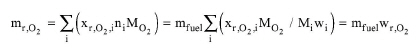
|
eq. (A.393)
|
where wr,O2 is the total mass of theoretical oxygen consumed per mass of fuel.
Air flow adjustment
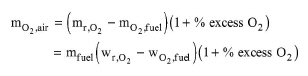
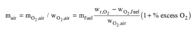
The flow of the air stream is always adjusted to match the specified percentage of excess oxygen. Based on this, the mass flow of oxygen in the air stream is calculated as:
|
|
eq. (A.394)
|
The mass flow rate of the air stream is then calculated as:
|
|
eq. (A.395)
|
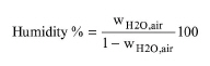
where wO2,air is the mass fraction of oxygen in the air stream. The humidity of air is calculated as percentage of dry air from the following expression:
|
|
eq. (A.396)
|
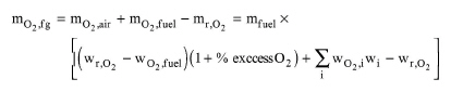
where wH2O,air is the mass fraction of water in the air stream (i.e., the mass fraction of the pure component that is associated with the water molecule through the “Components” tab). The remaining mass flow of unburned oxygen, which is transferred to the flue gas stream, is calculated as:
|
|
eq. (A.397)
|
Heat of combustion
From the stoichiometry of the combustion reactions, the molar heat of combustion of each fuel component is calculated as:
|

|
eq. (A.398)
|
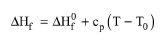
where ΔHf is the molar enthalpy of formation of each molecule. This is calculated as:
|
|
eq. (A.399)
|
where:
● ΔH0f is the standard enthalpy of formation of the molecule,
● Cp is the mean specific heat capacity of the molecule,
● T0 is the temperature at which the standard enthalpies of formation are given (25 oC), and
● T is the reference temperature used for enthalpy calculations by the program.
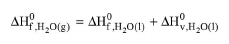
The standard enthalpies of formation of fuel components and of pure component associated with combustion products (CO2, H2O, SO2, and O2) are taken from the program’s pure component database. However, the standard enthalpy of formation of the pure component that is associated with H2O is assumed to correspond to liquid water. For example, by default the standard enthalpy of formation of the “Water” pure component is -285.83 kJ/mol, which corresponds to liquid water. This is converted into standard enthalpy of formation of water vapor, as follows:
|
|
eq. (A.400)
|
where ΔH0v is the latent heat of vaporization of water at 25 oC (which is assumed equal to 44 kJ/mol).
The total heat of combustion of the fuel stream expressed in units of energy per unit mass of fuel stream is calculated as:
|

|
eq. (A.401)
|
Overall energy balance
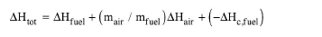
The total heat in the (furnace) system expressed in units of energy per unit mass of fuel stream can be calculated as:
|
|
eq. (A.402)
|
where:
● ΔHfuel is the specific enthalpy of the fuel stream,
● ΔHair is the specific enthalpy of the air stream,
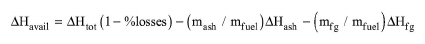
The net heat that is available for steam generation in the boiler expressed in units of energy per unit mass of fuel can be calculated as:
|
|
eq. (A.403)
|
where:
● %losses is the percent of overall heat losses to the surroundings,
● mash is the mass flow rate of the ash stream,
● ΔHash is the specific enthalpy of the ash stream,
● mfg is the mass flow rate of the flue gas stream, and
● ΔHfg is the specific enthalpy of the flue gas outlet stream.
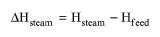
The specific enthalpy change of feedwater into steam (heat required for steam generation expressed in units of energy per unit mass of steam) is calculated as:
|
|
eq. (A.404)
|
where:
● Hsteam is the specific enthalpy of steam, and
● Hfeed is the specific enthalpy of feedwater.
By default, the properties of feedwater and steam are calculated based on the default pure component properties. Optionally, the properties of steam at the outlet can be calculated using the built-in Steam Calculator.
In the boiler, the net heat transfer to steam must be equal to the enthalpy change of feedwater into steam. Based on this equation, the following fuel/steam ratio (fuel requirement for steam generation) may be calculated:
|

|
eq. (A.405)
|
where msteam is the mass flow rate of steam.
Feedwater/fuel flow adjustment
The following flow adjustment options are available for solving eq. (A.405):
a) Adjust Feedwater Flow to Available Heat.
b) Adjust Fuel flow to Required Heat.
If option (a) is selected, the flow of the fuel stream is set by the user and the flow of steam is calculated from the above equation. The flow of feedwater is set equal to the calculated flow of steam.
If option (b) is selected, the flow of feedwater is set by the user and the flow of fuel is calculated from the above equation.
Steam Pressure and Temperature
The following specification options are available for the pressure of generated steam:
a) Set by User.
b) Equal to Pressure of Feed stream.
If option (a) is selected, the specified steam pressure can be greater than or equal to the pressure of feedwater. If the pressure of steam is higher than the pressure of feedwater, it is implied that feedwater is compressed by a pump to the specified pressure prior to entrance into the steam generator.
If option (b) is selected, the pressure of steam is set equal to the pressure of feedwater. Therefore, feedwater must be at the desired steam pressure prior to entrance into the steam generator.
The following specification options are available for the temperature of generated steam:
a) Set by User.
b) Equal to Saturation Temperature at Steam Pressure.
If option (b) is selected, then it is assumed that the steam generator produces saturated steam at the specified steam pressure. If option (a) is selected, the specified temperature can be anything: if it is higher than the saturation temperature, then superheated steam will be produced; if it is equal to the saturation temperature, then saturated steam will be produced; if it is lower than the saturation temperature, then hot water will be produced (not steam).
Flue Gas / Ash Streams
The following component flows are transferred to the flue gas stream:
a) Nitrogen, water, and additional gaseous inert components contained in fuel and air streams.
b) Combustion gases and unburned oxygen.
c) Fraction of fuel ash that is entrained in the flue gas stream.
The following component flows are transferred to the ash stream:
a) Remaining fuel ash.
b) Inert liquid/solid components of fuel and air streams.
Note that the temperatures of the flue gas and ash streams are set to the specified values (Steam Generation: Oper. Conds Tab). The pressure of these streams is set equal to the operating pressure in the steam generator which is taken to be equal to the ambient pressure; for more details on setting the ambient pressure, see Physical State Calculation Options
Equipment Sizing
In Design mode, the user specifies the maximum throughput of the steam generator. If the operating throughput exceeds the maximum throughput, the program assumes multiple units operating in parallel with a total throughput equal to the calculated throughput.
If the equipment size option is in Rating Mode, the user specifies the rated throughput and the number of units. If the calculated throughput per unit exceeds the rated throughput, a warning message is displayed advising the user to increase the rated throughput or number of units, or reduce the mass flow rate of the feedwater stream.
References
1. Niessen, W. R (2002). Combustion and Incineration Processes, Third Edition, Marcel Dekker, Inc.
2. Garrett, D.E. (1989). Chemical Engineering Economics, Springer.
Steam Generation: Modeling Assumptions & Constraints
● If option Adjust Feedwater Flow to Available Heat is selected, then the flow of the fuel stream must be non-zero. On the other hand, if option Adjust Fuel Flow to Required Heat is selected, then the flow of the feedwater stream must be non-zero.
● Only the fuel stream can contain combustible components. If the air stream contains combustible fuel components, then combustion of these components is ignored.
● If the built-in Steam Calculator is used, then the properties of the steam outlet stream are calculated by assuming that the feedwater stream is all water (even if the feedwater stream contains other components than water).
● If the built-in Steam Calculator is used, the specified values for the temperature and pressure of steam and feedwater must be within valid range. That is: Generally, (T, P) must be greater than the triple point (0°C, 611.657 Pa) and lower than or equal to (2000°C, 100 MPa). Specifically, if the temperature of steam is assumed equal to the corresponding saturation temperature, the specified steam pressure must be within the limits of the VLE curve for water (611.213 Pa – 22.064 MPa).
● If the pressure of steam is higher than the pressure of feedwater, it is implied that the feedwater is compressed by a pump to the specified pressure prior to entrance into the steam generator.
Steam Generation: Interface
The interface of this operation has the following tabs:
● Oper. Cond’s, see Steam Generation: Oper. Conds Tab
● Elem. Comp, see Steam Generation: Elemental Composition Tab
● Components, see Steam Generation: Components Tab
● Labor, etc, see Operations Dialog: Labor etc. Tab
● Description, see Operations Dialog: Description Tab
● Batch Sheet, see Operations Dialog: Batch Sheet Tab
● Scheduling, see Operations Dialog: Scheduling Tab