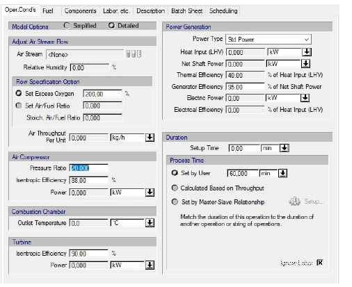
The following table shows a brief description of the variables appearing in this tab. The table also displays their default values and their generally acceptable range.
|
Variable |
Default Value |
Range |
|
|
||
|
○ Air Stream |
<None> |
Designated Air Stream |
|
● Relative Humidity (%) |
0.0 |
Positive |
|
◙ Excess Oxygen (%) |
200.0 |
Positive |
|
◙ Air-Fuel Ratio |
0.0 |
Positive |
|
● Stoichiometric Air-Fuel Ratio |
0.0 |
Positive |
|
● Air Throughput per Unit |
0.0 |
Positive |
|
○ Air Compressor Pressure Ratio (-) |
20.0 |
Positive |
|
○ Air Compressor Isentropic Efficiency (%) |
88.0 |
0-100 |
|
● Air Compressor Power (kW) |
0.0 |
Positive |
|
● Combustion Chamber Outlet Temperature (oC) |
0.0 |
Positive |
|
○ Turbine Isentropic Efficiency (%) |
90.0 |
0-100 |
|
● Turbine Power (kW) |
0.0 |
Positive |
|
○ Power Type |
<Std Power> |
Any Power Type |
|
● Heat Input (LHV) (kW) |
0.0 |
Positive |
|
● Net Shaft Power (kW) |
0.0 |
Positive |
|
● Thermal Efficiency (%) |
0.0 |
0-100 |
|
○ Generator Efficiency (%) |
95.0 |
0-100 |
|
● Electric Power |
0.0 |
Positive |
|
● Electrical Efficiency (%) |
0.0 |
0-100 |
|
○ Setup Time |
0.0 |
Positive |
|
◙ Process Time (min) |
60.0 |
Positive |
|
○ Ignore Labor? |
Yes |
Yes/No |
Symbol Key: ○ User-specified value (always input); ● Calculated value (always output); ◙ Sometimes input, sometimes output
The following list describes the available specification choices in this tab; for more details on how these are implemented, see Power Generation in a Gas Turbine-Generator: Modeling Calculations.
•Model options...
You may either choose the “detailed” or the “simplified” model. If you choose the “detailed” model, you must specify the compressor efficiency and turbine efficiency. On the other hand, if you choose the “simplified” model, you must specify the gas turbine’s thermal efficiency.
•Duration options...
Duration options are only available in batch mode. You can set the process time, or have the process time calculated based on air throughput, or match the duration of this operation to the duration of another operation by introducing a master-slave relationship between the two operations. If you introduce a master-slave relationship, the program will match the setup time, the process time and the turnaround time of this operation (the ‘slave’) with the corresponding times of the reference operation (the ‘master’ operation). For more details on how to setup a master-slave relationship, see The Scheduling Tab.