This operation is used to model the conversion of a fuel’s chemical energy into electricity through the electrochemical (redox) reaction of the fuel with an oxidizing agent in a fuel cell. Usually, the fuel is hydrogen and the oxidizing agent is air or oxygen.
A fuel cell basically consists of three segments: an anode, an electrolyte, and a cathode. The fuel is fed through the anode channel on one side of the fuel cell, while oxidant is fed through the cathode channel on the other side of the cell. On the anode catalyst, positively charged ions (or waste molecules) are produced together with electrons. On the cathode catalyst, waste molecules (or negatively charged ions) are produced. The electrolyte is a substance specifically designed so ions can pass through it, but the electrons cannot. The electrons are forced to travel from the anode to the cathode through an external circuit, producing direct current electricity. Overall, the fuel cell produces electricity, heat and waste (water and sometimes carbon dioxide).
For example, in a proton exchange membrane (PEM) fuel cell, hydrogen gas is fed through the anode and oxygen gas is fed through the cathode. On the anode catalyst, the hydrogen is converted into positively charged hydrogen ions (protons) and electrons. The protons travel to the cathode through the electrolyte (proton conducting membrane) and the electrons travel to the cathode through the external circuit. On the cathode catalyst, the protons are reunited with the electrons and the two react with the oxygen molecules to form water. The overall reaction is that of water formation.
Another example is the solid fuel oxide (SOFC) fuel cell where a fuel containing hydrogen is fed through the anode and oxygen gas is fed through the cathode. On the cathode catalyst, the oxygen gas absorbs electrons to create negatively charged oxygen ions. The oxygen ions then travel through the electrolyte (solid ceramic material) to the anode. On the anode catalyst, the oxygen ions react with hydrogen to produce water and electricity. Again, the overall reaction is that of water formation. However, carbon dioxide may also be a by-product depending on the fuel.
● Power Generation in a Fuel Cell Procedure
Fuel (e.g., hydrogen) and oxidizing agent (e.g., oxygen) are fed to the fuel cell through dedicated input ports for fuel (“Fuel Inlet”) and oxidant (“Oxidant Inlet”), respectively. In the fuel cell, the fuel and oxidant react according to the specified reaction (e.g., water formation). Any unreacted fuel and oxidizing agent leave the fuel cell through dedicated output ports for fuel (“Fuel Outlet”) and oxidant (“Oxidant Outlet”), respectively. If the “Positive Ion Transfer (from Anode to Cathode)” option is chosen, the reaction is assumed to occur on the oxidant (cathode) side and the reaction products leave the fuel cell through the “Oxidant Outlet” port. On the other hand, if the “Negative Ion Transfer (from Cathode to Anode)” option is chosen, then the reaction is assumed to occur on the fuel (anode) side and the reaction products leave the fuel cell through the “Fuel Outlet” port.
To account for ion movement, the following two cases are considered:
● Positive Ion Transfer (from Anode to Cathode)
● Negative Ion Transfer (from Cathode to Anode)
If the “Positive Ion Transfer (from Anode to Cathode)” option is chosen, then any pure component contained in the fuel feed stream that participates in the specified reaction as reactant is assumed positively charged and it is transferred to the oxidant (cathode) side. The reaction is assumed to take place on the cathode side and the reaction products are transferred out through the “Oxidant Outlet” port. Any unreacted fuel is transferred out through the “Fuel Outlet” port.
If the “Negative Ion Transfer (from Cathode to Anode)” option is chosen, then any pure component contained in the oxidant feed stream that participates in the specified reaction as reactant is assumed negatively charged and it is transferred to the fuel (anode) side. The reaction is assumed to take place on the anode side and the reaction products are transferred out through the “Fuel Outlet” port. Any unreacted oxidant is transferred out through the “Oxidant Outlet” port.
For the reaction, the user provides the mass or molar stoichiometric coefficients (Ai) of the various components and the extent of reaction (x) based on either the limiting component or a reference component. Negative stoichiometric coefficients are used for reactants and positive for products. The coefficients can be supplied in either mass or molar units. The algorithm used by the program to perform the material balances is explained below.
If the extent of the reaction is expressed based on the limiting component then, first of all, the limiting component is identified. This is done based on the mass stoichiometry and the composition of the reacting mixture. If the extent of the reaction is expressed based on a user-defined component, then first of all, the program attempts to validate that the user-defined conversion is achievable (i.e., there are enough reactants for the reaction to proceed to such an extent). If that is not the case, then the conversion (x) is adjusted to reflect the maximum achievable conversion percentage (based on the extent-component chosen by the user).
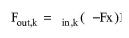
For the limiting component (k) or the extent-reference component (depending on what is the case), the following holds:
|
|
where:
● Fout,k s the mass flowrate of the component after the reaction,
● Fin,k is the mass flowrate of the component before the reaction, and
● x is the (possibly adjusted) reaction extent.
Now, the mass flowrate after the reaction (Fout,i) of any other component present (i) is given by the following equation as a function of its mass flowrate (Fin,i) before the reaction, the extent of reaction (x), and the mass stoichiometric coefficients (Ai):
|
|
where Ak is the coefficient of the limiting or extent-reference component.
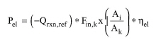
The specified reaction must be exothermic and therefore, the specified specific heat of reaction (“Reaction Enthalpy”) (expressed as energy per unit mass of enthalpy-reference component) must be negative. This is converted into electricity and thermal energy as follows:
|
|
eq. (A.442) |
|
|
where:
● Pel is the electric power output (in kW),
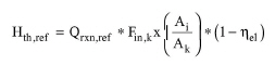
● Qrxn,ref is the specified specific heat of reaction at the user-defined enthalpy-reference conditions (temperature and component physical states) (in kJ/kg of reference component),
● Fin,kx(Ai/Ak) is the mass flow rate of reacted or produced enthalpy-reference component (in kg/s),
● ηel is the electric efficiency, and
● Hth,ref is the net heat of reaction (the part of the heat of reaction that is converted into thermal energy) at the user-defined enthalpy-reference conditions (temperature and component physical states) (in kW).
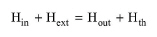
To estimate the overall heating or cooling requirements, or the exit temperature, the program solves the following overall energy balance:
|
|
eq. (A.444) |
where:
● Hin is the enthalpy of reactants (in kW),
● Hext is the external heat duty (in kW),
● Hout is the enthalpy of products (in kW),
● Hth is the net enthalpy of reaction (in kW),
Note that the above enthalpy terms are based on the flowsheet’s enthalpy calculation reference conditions (0oC, 1 atm, and liquid state, by default). To view or edit the flowsheet’s enthalpy calculation reference conditions, right click on white space and click Reference Conditions. To convert the net enthalpy of reaction at user-defined enthalpy-reference conditions (Hth,ref) into net enthalpy of reaction at the flowsheet’s enthalpy reference conditions (Hth), the overall energy balance equation is used.
Also note that the cooling duty (Hc) is equal to -Hext.
The following thermal mode options are available:
● Set Final Temperature
● Adiabatic
● Set Cooling Duty
If the exit temperature is set, the program first calculates Hout based on the specified exit temperature. Then, the overall energy balance is solved to calculate the value of Hext.
In the adiabatic case, Hext=0 and the overall energy balance is solved to calculate Hout. Then, the exit temperature is estimated based on the value of Hout.
If the cooling duty is set, then Hext = -Hc and the overall energy balance is solved to calculate Hout and, based on this, the exit temperature.
In Design mode, the user specifies the maximum power output of the fuel cell. If the electric power produced by the operation exceeds the maximum power output, the program assumes multiple units operating in parallel with a total power output equal to the calculated electric power.
If the equipment size option is in Rating Mode, the user specifies the rated power output and the number of units. If the calculated electric power per unit exceeds the rated power output, a warning message is displayed advising the user to increase the rated power output or number of units, or reduce the mass flow rates of the reactants.
1. Harrison K.W., Remick R. and G.D. Martin. Hydrogen Production: Fundamentals and Case Study Summaries. NREL/CP-550-47302 (http://www.nrel.gov/hydrogen/pdfs/47302.pdf), 2010.
2. Evaluation of Stationary Fuel Cell Deployments, Costs, and Fuels. NREL/PR-5400-60903 (http://www.nrel.gov/docs/fy14osti/60903.pdf), 2013.
The interface of this operation has the following tabs:
● Oper. Cond’s, see Power Generation in a Fuel Cell: Oper. Conds Tab
● Reaction, see Power Generation in a Fuel Cell: Reaction Tab
● Labor, etc, see Operations Dialog: Labor etc. Tab
● Description, see Operations Dialog: Description Tab
● Batch Sheet, see Operations Dialog: Batch Sheet Tab
● Scheduling, see Operations Dialog: Scheduling Tab