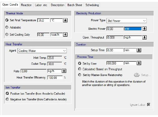
The following table shows a brief description of the variables appearing in this tab. The table also displays their default values and their generally acceptable range:
|
Variable |
Default Value |
Range |
|
|
||
|
◙ Final Temperature (oC) |
35.0 |
Positive |
|
◙ Cooling Duty (kcal/h) |
0.0 |
Positive |
|
○ Heat Transfer Agent |
<Cooling Water> |
Any Heat Transfer Agent |
|
● Inlet Temp. (oC) |
5.0 |
Positive |
|
● Outlet Temp. (oC) |
10.0 |
Positive |
|
● Rate (kg/h) |
0.0 |
Positive |
|
○ Power Type |
<Std Power> |
Any Power Type |
|
● Electric Power (kW) |
0.0 |
Positive |
|
● Operating Throughput (kg/h) |
0.0 |
Positive |
|
○ Setup Time (min) |
0.0 |
Positive |
|
◙ Process Time (min) |
60.0 |
Positive |
|
○ Ignore Labor? |
Yes |
Yes/No |
Symbol Key: ○ User-specified value (always input); ● Calculated value (always output); ◙ Sometimes input, sometimes output
The following list describes the available specification choices in this tab; for more details on how these are implemented, see Power Generation in a Fuel Cell: Modeling Calculations.
•If you select the ‘Negative Ion Transfer (from Anode to Cathode)’ option...
Positive ions travel from the fuel stream (anode) to the oxidant stream (cathode) through the electrolyte. At the cathode, the positive ions react with the oxidant and the reaction products leave the fuel cell through the Oxidant Outlet stream. For example, if the fuel is hydrogen and the oxidant is oxygen, then hydrogen ions travel from the anode to the cathode, where they react with oxygen to produce water, which leaves the fuel cell through the Oxidant Outlet stream. This is similar to what happens in a PEM fuel cell.
•If you select the ‘Negative Ion Transfer (from Cathode to Anode)’ option...
Negative ions travel from the oxidant stream (cathode) to the fuel stream (anode) through the electrolyte. At the anode, the negative ions react with the fuel and the reaction products leave the fuel cell through the Fuel Outlet stream. For example, if the fuel is hydrogen and the oxidant is oxygen, then oxygen ions travel from the cathode to the anode, where they react with hydrogen to produce water, which leaves the fuel cell through the Fuel Outlet stream.