This operation simulates a membrane regeneration step in flow-through and bind-and-elute chromatographies which is used to restore the membrane to its initial state. The main objective of this operation is to determine bufffer consumption. By default, any change that may occur in the membrane’s retained mass during this step is ignored. Optionally, the entire membrane contents may be removed to the buffer outlet stream.
● Membrane Adsorption Procedure in Flow-Through Mode
● Membrane Adsorption Procedure in Bind-and-Elute Mode
You need to specify the values of two out of the following three variables: buffer flowrate, buffer volume, and process time time. The value of the remaining variable will be calculated by the model as explained below.
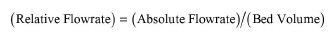
If a buffer flowrate is set, you can specify any one of the following three variables: linear velocity, absolute flowrate, or relative flowrate. The other two variables will be calculated by the program according to the following equations:
|
|
|
|
where ‘Bed Volume’ denotes the membrane’s volume in the context of this operation.
If a buffer flowrate is not set, then the absolute flowrate will be calculated by the program based on eq. (A.174).
If a buffer volume is set (per batch cycle and equipment unit), then you can either set an absolute volume or a relative volume (in membrane volumes). The buffer’s absolute volume is equal to its relative volume times the membrane’s volume. This relation is used to determine the absolute volume based on a relative volume, and vice versa. If a buffer volume is not set, then the absolute volume will be calculated by the program based on eq. (A.174).
The process time can be either set by user or calculated from the absolute values of buffer flowrate and volume as follows:
|
|
where ‘Feed Volume’ denotes buffer volume in the context of this operation
The user must specify the buffer’s inlet and outlet (waste) stream ports and the inlet stream’s composition. The program will auto-adjust the total flow of the inlet stream (and, thereby, the flows of individual components in it) based on the buffer’s volume per batch cycle and per equipment unit.
|
|
As far as the inlet stream is concerned, you only need to specify a valid composition for that stream and not worry about total stream flow (since the flowrate of the buffer’s inlet stream will be auto-adjusted by the program). |
All components of the buffer’s inlet stream end up in the buffer’s outlet (waste) stream. If the option ‘Remove Membrane Contents’ is checked, then the entire membrane contents are also removed from the membrane and added to the buffer’s outlet (waste) stream.
The interface of this operation has the following tabs:
● Oper. Cond’s, see MA Regeneration: Oper. Conds Tab
● Labor, etc, see Operations Dialog: Labor etc. Tab
● Description, see Operations Dialog: Description Tab
● Batch Sheet, see Operations Dialog: Batch Sheet Tab
● Scheduling, see Operations Dialog: Scheduling Tab