This operation simulates a membrane loading step in flow-through chromatography where (typically but not necessarily) the target protein flows through and impurities bind to the membrane. The main objectives of this operation are to determine process time, account for retained mass in the membrane and, if in Design Mode, determine the required number of units (holders/cartridges).
● Membrane Adsorption Procedure in Flow-Through Mode
Equipment sizing is based on the specification of a reference membrane capacity. This can be expressed as the ratio of a reference amount to a reference basis. The reference basis can be either the membrane’s area or the membrane’s volume. Two options are available for specifying the reference amount:
● Set Loading Capacity of a Key Component.
● Set Total Binding Capacity.
The loading capacity in terms of a key component refers to the maximum inlet mass of that that can be processed by the membrane. The total binding capacity refers to the maximum mass of all components (except those ‘ignored in sizing’ as explained below) that can bind to the membrane. The loading capacity and the total binding capacity can be estimated experimentally.
You also need to specify the retained mass % for each component. This is the percentage of the mass of that component in the feed stream that is retained in the membrane. In the case that the ‘Set Total Binding Capacity’ option is selected, the retained mass of all components is considered bound to the membrane by default. If a component’s retained mass is not bound, or if that component is not considered when the binding capacity is determined, you can instruct the program to ignore that component in sizing calculations by checking the ‘Ignore in Sizing ?’ box next to it.
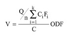
The required membrane volume per cycle, V, can be calculated as:
|
|
Where:
● Q is the volume of material processed by the membrane per plant batch time.
● n is the number of cycles per batch.
● k is the total number of components in the feed stream.
● Ci is the concentration of component ‘i’ in the feed stream.
● Fi is the retained % that is assigned to component ‘i’ for equipment sizing purposes; if the loading capacity of a key component is set, then Fi is set to 1.0 for the key component and 0.0 for any other component; if the total binding capacity is set, then there are two possibilities: (a) if the ‘Ignore in Sizing ?’ option is checked, Fi is set to 0.0; (b) if the ‘Ignore in Sizing ?’ option is not checked, Fi is set equal to the specified retained %.
● C is either the key component loading capacity per volume or the total binding capacity per volume depending on which type of membrane capacity is specified.
● ODF is the overdesign factor.
If V > V0, where V0 is the membrane volume per equipment unit (holder or cartridge), then multiple units operating in parallel are assumed.
In terms of loading flowrate, you can specify any one of the following three variables: linear velocity, absolute flowrate, or relative flowrate. The other two variables will be calculated by the program according to the following equations:
|
|
|
|
where ‘Bed Volume’ denotes the membrane’s volume in the context of this operation.
The process time is calculated using the following equation:
|
|
where ‘Feed Volume’ denotes buffer volume in the context of this operation
For each component, a percentage of the corresponding amount in the feed stream equal to the specified retained mass % is retained in the membrane. Everything else is exits through the designated flow-through output (top outlet) port.
The cost associated with membrane replacement is estimated as for all consumables (see Consumables Cost). For membranes that last several years, the user may decide to depreciate the first membrane fill-in by checking the ‘Is First Cartridge Capitalized’ check box in the equipment’s Consumables tab.
The interface of this operation has the following tabs:
● Oper. Cond’s, see MA Flow-Through: Oper. Conds Tab
● Labor, etc, see Operations Dialog: Labor etc. Tab
● Description, see Operations Dialog: Description Tab
● Batch Sheet, see Operations Dialog: Batch Sheet Tab
● Scheduling, see Operations Dialog: Scheduling Tab


