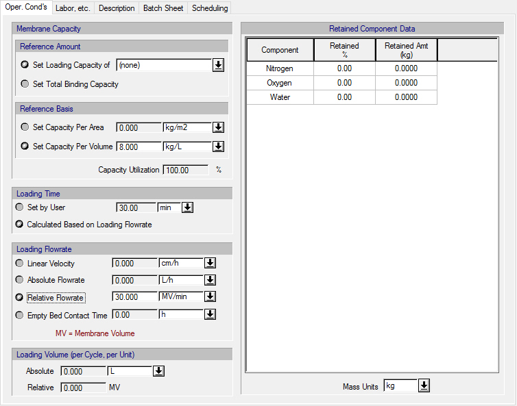
This tab appears on the interface dialog of the the following operation:
● Membrane Adsorber (MA) Flow-Through
The following table shows a brief description of the variables appearing in this tab. The table also displays their default values and their generally acceptable range:
|
Variable |
Default Value |
Range |
|
|
||
|
○ Key Component (for Loading Capacity Specification) |
<None> |
Any Comp. |
|
◙ Membrane Capacity Per Area (kg/m2) |
0.0 |
Positive |
|
◙ Membrane Capacity Per Volume (g/L) |
8000.0 |
Positive |
|
● Capacity Utilization (%) |
100.0 |
0 - 100 |
|
◙ Linear Velocity (cm/h) |
0.0 |
Positive |
|
◙ Absolute Flowrate (L/h) |
0.0 |
Positive |
|
◙ Relative Flowrate (MV/min) |
30.0 |
Positive |
|
● Absolute Loading Volume (per Cycle, per Unit) (L) |
0.0 |
Positive |
|
● Relative Loading Volume (per Cycle, per Unit) (MV) |
0.0 |
Positive |
|
○ Retained % |
0.0 |
0 – 100 |
|
● Retained Amt (kg) |
0.0 |
Positive |
|
○ Ignore in Sizing? |
No |
Yes/No |
Symbol Key: ○ User-specified value (always input); ● Calculated value (always output); ◙ Sometimes input, sometimes output
The following list describes the available specification choices in this tab; for more details on how these are implemented, see MA Flow-Through: Modeling Calculations.
•If the ‘Set Loading Capacity of <Component>’ option is selected...
You must select a key component and specify the membrane’s loading capacity with respect to that component, either per membrane area or volume.
•If the ‘Set Total Binding Capacity’ option is set...
You must specify the mebrane’s total binding capacity per membrane area or volume. Optionally, you may ignore a component from equipment sizing calculations by checking the ‘Ignore in Sizing?’ box next to that component.
•If the ‘Set Capacity Per Area’ option is set...
You must specify the membrane capacity per membrane area. The program will calculate the respective membrane capacity per membrane volume.
•If the ‘Set Capacity Per Volume’ option is set...
You must specify the membrane capacity per membrane volume. The program will calculate the respective membrane capacity per membrane area.
•If the Loading Flowrate is set to ‘Linear Velocity’...
You must specify the linear velocity of the feed stream. The program will calculate the corresponding absolute flowrate and relative flowrate values.
•If the Loading Flowrate is set to ‘Absolute Flowrate’...
You must specify the absolute flowrate of the feed stream. The program will calculate the corresponding linear velocity and relative flowrate values.
•If the Loading Flowrate is set to ‘Relative Flowrate’...
You must specify the relative flowrate of the feed stream. The program will calculate the corresponding linear velocity and absolute flowrate values.