This operation is used to simulate the reaction and separation process phenomena that occur inside a rotary kiln. These include the combustion reactions that take place in the kiln’s burner, the pyroprocessing reactions that take place in the kiln, and the entrainment of solids in the gas phase, which also takes place in the kiln. The combustion and pyroprocessing reactions are described by stoichiometry. The combustion of fuel and air is described using built-in stoichiometric reactions. The pyroprocessing reactions must be set by the user.
This operation can be used to simulate the conversion of raw materials such as limestone and clay into cement clinker in a rotary cement kiln. In the rotary cement kiln, a mixture consisting primarily of limestone and clay is fed into the upper end of a rotary cement kiln, which is basically a slightly inclined cylindrical vessel. As the kiln rotates slowly about its longtitudinal axis, the process feedstock moves slowly from the upper end of the kiln towards the lower end. At the lower end, a burner is used to generate hot gases by burning fuel and air. As the kiln moves, it is heated by the hot combustion gases flowing counter-currently, which causes the formation of cement clinker.
● Continuous Stoichiometric Reaction Procedure in a Rotary Kiln
Continuous Stoichiometric Reaction in a Rotary Kiln: Modeling Calculations
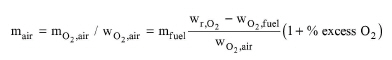
The flow of the air stream is always adjusted to match the specified percent excess oxygen of the air-fuel mixture or the specified air-fuel ratio. If the percent excess oxygen is specified, the mass flow rate of the air stream is calculated as:
|
|
where mair is the mass flow rate of the air stream, mO2,air is the stoichiometric mass flow rate of oxygen in the air stream, wO2,air is the mass fraction of oxygen in the air stream, mfuel is the mass flow rate of the fuel stream, wr,O2 is the theoretical mass of oxygen required for complete combustion of the fuel stream per unit mass of fuel stream, and wO2,fuel is the available mass of oxygen in the fuel stream (which is the sum of total fuel elemental oxygen and fuel stream oxygen) per unit mass of fuel stream. The calculation of wr,O2 and mO2,air is described in the section that describes the mass balances of combustion reactions.
The relative humidity of air is calculated by dividing the partial pressure of water vapor in the air stream by the saturation pressure of water vapor at the specified air stream temperature. The partial pressure of water vapor in the air stream is calculated by multiplying the pressure of the air stream by the mol fraction of water vapor in the air stream. The saturation pressure of water vapor at the specified air stream temperature is calculated from the saturated vapor pressure (Antoine) correlation for the pure component which is associated with water through the Fuel-Air Combustion: Components Tab.
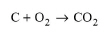
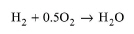
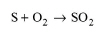
The model considers the complete combustion of combustible fuel elements C, H and S into carbon dioxide, water vapor and sulfur dioxide, respectively, in the presence of stoichiometric or excess oxygen. For each pure component of the fuel stream that is set by the user as a combustible fuel (e.g., coal, natural gas, etc.), its elemental C, H, O, N and S composition must be specified (see Fuel-Air Combustion: Fuel Tab). If the fuel contains additional elements, then these may be added to the composition of elemental N or to the composition of Ash. In addition, any gaseous components that exist in the combustion products (i.e., carbon dioxide, water, sulfur dioxide, oxygen) must be associated explicitly with a registered pure component (see Fuel-Air Combustion: Components Tab).
The elemental oxygen contained in the fuel is assumed to participate in combustion reactions with C, H and S. The elemental nitrogen contained in the fuel is taken to appear as gaseous nitrogen in the combustion products. The reaction of nitrogen contained in the air with oxygen and hydrocarbons is not considered. Only the following combustion reactions are considered:
|
|
|
|
|
|
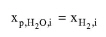
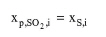
From the stoichiometry of the above reactions, the moles of combustion gases CO2, H2O and SO2 produced per mole of fuel component i from the complete combustion of that component are calculated as:
|
|
|
|
|
|
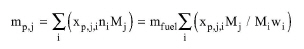
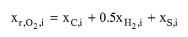
where xC,i, xH2,i and xS,i are the respective moles of elemental carbon, elemental hydrogen and elemental sulfur per mole of fuel component i. The total mass flow rate of combustion gas j (j=CO2, H2O, or SO2) produced by complete combustion of all combustible fuel components can be calculated as:
|
|
where Mj is the molecular weight of combustion gas j, ni is the mole flow of fuel component i, Mi is the molecular weight of fuel component i, and wi is the mass fraction of fuel component i.
The theoretical moles of oxygen required for the complete combustion of fuel component i per mole of that fuel component can be calculated as:
|
|
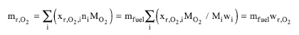
Then, the total mass flow rate of theoretical oxygen required for the complete combustion of all fuel components can be calculated as:
|
|
where wr,O2 is the theoretical mass of oxygen required for complete combustion of the fuel per unit mass of fuel. The stoichiometric air-fuel ratio displayed on the interface of this operation can then be calculated by dividing mr,O2 by the mass flow rate of the fuel stream.
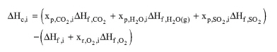
From the stoichiometry of the combustion reactions, the molar heat of combustion of each fuel component is calculated as:
|
|
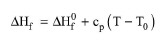
where ΔHf is the molar enthalpy of formation of each molecule. This is calculated as:
|
|
where:
● ΔH0f is the standard enthalpy of formation of the molecule,
● Cp is the mean specific heat capacity of the molecule,
● T0 is the temperature at which the standard enthalpies of formation are given (25 oC), and
● T is the reference temperature used for enthalpy calculations by the program.
The lower heating value (LHV) of each fuel component corresponds to the negative value of the standard enthalpy of combustion (LHVi=-ΔΗoc,i). This can be calculated from eq. (A.398), if ΔHf is substituted by ΔHof for all molecules.
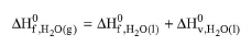
The standard enthalpies of formation of fuel components and of pure component associated with combustion products (CO2, H2O, SO2, and O2) are taken from the program’s pure component database. The standard enthalpy of formation of the “Water” component included in the Designer database (-285.83 kJ/mol) corresponds to liquid water. In a similar manner, the standard enthalpy of formation of the pure component that is associated with H2O is assumed to correspond to liquid water. This is converted into standard enthalpy of formation of water vapor, as follows:
|
|
where ΔH0v is the latent heat of vaporization of water at 25 oC (which is assumed equal to 44 kJ/mol).
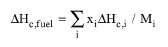
The total heat of combustion of the fuel stream expressed in units of energy per unit mass of fuel stream is calculated as:
|
|
where xi is the mass fraction of fuel component i in the fuel stream.
The operating pressure is taken to be equal to the pressure of the inlet air stream.
In the kiln, the feed stream and the combustion products are available to react. The reactions that take place in the kiln must be set by the user. Typical reactions in cement clinker production include calcination (CaCO3->CaO+CO2), ferrite (C4AF) formation (Al2O3+4CaO-->Fe2O3+4CaO*Al2Fe2O6), alite (C3S) formation (3CaO+SiO2-->3CaO*SiO2), belite (C2S) formation (2CaO+SiO2-->Ca2SiO4), and tricalcium aluminate (C3A) formation (Al2O3+3CaO-->3CaO*Al2O3).
For more information on how the material balances are done for a set of stoichiometric reactions, see Stoichiometric Reaction Operations: Modeling Calculations.
After the stoichiometric reactions in the kiln are done, the reaction products are split into liquid/solid products and gaseous products based on the specified product temperature, the operating temperature, and the specified physical state toolbox of the procedure. Furthermore, for each liquid/solid product, a percentage equal to the specified entrainment % is transferred to the gaseous product to account for solids entrainment.
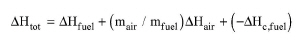
The total heat input in the combustion chamber expressed in units of energy per unit mass of fuel stream can be calculated as:
|
|
where ΔHfuel is the specific enthalpy of the fuel stream and ΔHair is the specific enthalpy of the air stream.
The overall energy balance in the kiln is this: mfuelΔHtot + mfeedΔHfeed-Qr= mpΔΗp +mgΔΗg + Qloss, where Qr is the total reaction enthalpy in the kiln, mp is the mass flow rate of the liquid/solid products, ΔΗp is the specific enthalpy of the liquid/solid products, mg is the mass flow rate of the exhaust gas, ΔΗg is the specific enthalpy of the exhaust gas, and Qloss are the heat losses to the surroundings. The heat losses are calculated by multiplying the specified Overall Heat Losses % by the heat of combustion (ΔHc,fuel) and by the mass flow rate of the fuel stream (mfuel). The above energy balance is solved for ΔΗg and then the exhaust gas temperature is calculated from that.
In Design Mode, the user specifies the Max Diameter and Length/Diameter Ratio. Based on these, the program calculates the maximum volume of a single rotary kiln that is available for purchase on the market. In addition, the user specifies the operation’s Specific Volumetric Loading and based on this, and on the calculated operating throughput (total mass flowrate of product), the program calculates the total kiln volume required for this operation. If the total kiln volume does not exceed the maximum kiln volume, a single unit of diameter equal to the total kiln volume is used. If the total kiln volume exceeds the maximum kiln volume, then multiple parallel identical units are used whose diameter is such that the sum of all kiln volumes is equal to the total volume requirement for this operation. In addition to calculating the number of units and diameter, the program also calculates the kiln’s length, rated capacity, lateral surface area and volume.
In Rating Mode, the user specifies the number of units as well as the kiln diameter and length. Based on these, the program calculates the length/diameter ratio, lateral surface area and volume. In addition, the user specifies the rated capacity of the rotary kiln, and if this is less than the operating throughput per unit, the program displays a warning to indicate that bigger equipment or more equipment is needed for this operation.
1. Peray, K. E., The Rotary Cement Kiln, Second Edition, Chemical Publishing Co., Inc., New York, N.Y., 1986.
The interface of this operation has the following tabs:
● Oper. Cond’s, see Continuous Stoichiometric Reaction in a Rotary Kiln: Oper. Conds Tab
● Fuel, see Fuel-Air Combustion: Fuel Tab
● Components, see Fuel-Air Combustion: Components Tab
● Reactions, see Stoichiometric Reaction/Fermentation Operation: Reactions Tab
● Utilities, see Throughput Operations: Utilities Tab
● Labor, etc, see Operations Dialog: Labor etc. Tab
● Description, see Operations Dialog: Description Tab
● Batch Sheet, see Operations Dialog: Batch Sheet Tab
● Scheduling, see Operations Dialog: Scheduling Tab