This operation can model any number of parallel or sequential reactions that take place in a Plug Flow Reactor (PFR). It supports a wide variety of reaction kinetics. The model assumes that the flow in the tube is radially isotropic (without mass or energy gradients) and that axial mixing is negligible.
● Continuous Kinetic Reaction Procedure in a PFR
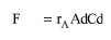
For a component A that enters a PFR, the component balance equation for a constant density system is given by the following equation:
|
|
or:
|
|
where F is the feed volumetric flowrate, Cin is the inlet concentration, C is the outlet concentration, A is the cross sectional area of the reactor, L is the length of the reactor, and rA is the combined reaction rate of component A (see eq. (A.43) - eq. (A.46). The above equations for each component constitute a system of ordinary differential equations that are integrated numerically to calculate the composition of the outlet stream.
For systems of variable reaction mixture density (which is often the case for gaseous reactions), the simplified material balance equation cannot be used. An excellent description of the formulation used in that case can be found in the literature (Fogler, 1992 - pp. 505-507).
For a PFR operating in a batch plant, the feed flowrate F is calculated by dividing the volume of material that needs to be processed per batch by the process time and the number of cycles per batch of the reactor unit. The number of cycles (a scheduling parameter) can be set through the Scheduling tab of the step’s dialog.
A PFR can operate isothermally (at a constant operating temperature), adiabatically (no exchange of heat with the surroundings), or with an evenly distributed heating or cooling duty along the length of the reactor. Under isothermal conditions, the model calculates the heating or cooling requirement along the length of the reactor and stores the values in the profiles (see ‘Profiles’ paragraph below). The heating/cooling duty displayed on the Operating Conditions tab in kcal/h represents averaged values over the whole reactor. Under conditions of specified heating or cooling, the model calculates the temperature of the reacting mixture along the length of the reactor and stores the values in the profiles. Adiabatic operation is a special case of specified heating or cooling duty.
The plug flow reaction operation can generate profiles of temperature, heating/cooling duty, and component concentration along the length of the reactor. See Kinetic Reaction Operations: Profiles Tab for information on how to initialize, view, and save the profiles (recorded data sets). Please note that in the case of a PFR the length of the reactor (instead of time) is the independent variable.
In Design Mode of calculation, the user specifies the residence time (tR) and the working to vessel volume ratio. The working (liquid) volume (Vw) and the vessel volume (V) are calculated using eq. (A.5) and eq. (A.55):
In Rating Mode, the user specifies the vessel volume, the number of units, and either the residence time or the working to vessel volume ratio. When the residence time is specified, the program calculates the working to vessel volume ratio using the above equations and checks to make sure that the calculated value is between the minimum and maximum working to vessel volume ratio. When the working to vessel volume ratio is specified, the program calculates the residence time using the above equations.
If this unit operates in a batch plant, the feed flowrate F is calculated by dividing the volume of material that needs to be processed per cycle by the process time.
1. Fogler, H. S. 1992. Elements of Chemical Reaction Engineering, 2nd edition, Prentice Hall.
The interface of this operation has the following tabs:
● Oper. Cond’s, see Cont. Stoich. RXN in PFR: Oper. Conds Tab
● Reactions, see Kinetic Reaction/Fermentation Operation: Reactions Tab
● Profiles, see Kinetic Reaction Operations: Profiles Tab
● Labor, etc, see Operations Dialog: Labor etc. Tab
● Description, see Operations Dialog: Description Tab
● Batch Sheet, see Operations Dialog: Batch Sheet Tab
● Scheduling, see Operations Dialog: Scheduling Tab
