The main objective of this operation is to estimate the elution time and the amount of buffer(s) required.
● Packed Bed Adsorption (PBA) Chromatography Procedure (Simplified)
● Expanded Bed Adsorption (EBA) Chromatography Procedure
For isocratic elution, the buffer volume is equal to the bed volume times the volume factor (in packed bed volumes) that is specified by the user. For gradient elution steps, the gradient buffer is generated by mixing two different buffers in continuously varying ratios. This is specified by identifying the two buffer streams (A and B) and by either providing the initial and final concentrations of a ‘key component’ in the gradient buffer, or the initial and final volumes of buffer A in the gradient buffer.
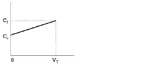
When the initial and final concentrations of a key component are specified, then in order to calculate the volumes of buffers A and B in the gradient elution buffer, it is assumed that the concentration of the key component in the gradient elution buffer varies linearly with the gradient elution buffer’s volume, as shown in the figure below:
In the above figure, C0 is the initial concentration of the key component in the gradient buffer, Cf is the final concentration of the key component in the gradient buffer, and VT is the gradient elution buffer volume.
To estimate the volumes of buffers A and B that are mixed to form the gradient elution buffer of volume VT we do the following simple material balances:
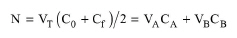
The total number of moles, N, of the key component contained in the gradient buffer of volume VT is given by:
|
|
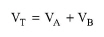
where VA, VB are the volumes of buffers A and B, respectively, required to form the gradient buffer of volume VT. CA and CB are the concentrations of the key component in buffers A and B, respectively. Also VT
|
|
is equal to:
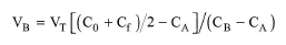
The above equations are solved for VA and VB and the answer for VB is given below:
|
|
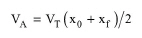
Similarly to the case that key component data is specified, when the initial (xo) and final (xf) volume percentages of buffer A in the gradient elution buffer are specified it is assumed that the volume % of buffer A in the gradient elution buffer varies linearly with the gradient elution buffer’s volume. Then, the volume of buffer A in the gradient elution buffer is given by:
|
|
The calculated buffer volumes are used to adjust the flowrates of the corresponding streams. If the streams have source unit procedures (e.g., buffer preparation tanks), the flowrate adjustment is recursively back-propagated till process feed streams are reached. At least one of the process feed streams that feed into elution or regeneration-equilibration-wash streams must have non-zero flowrate.
In terms of elution flowrate you can either specify the linear velocity, the absolute flowrate, or the relative flowrate:
|
|
|
|
The process time is calculated using the following equation:
|
|
The feed (buffer) volume in the above equation is expressed in ‘packed bed volumes’.
A column may be used to bind either product component(s) or impurity components (specified by the Resin’s Primary Function buttons on the Loading operation dialog).
In the first case (retention of product components), for a component that binds to the resin its amount in the product stream is equal to its amount in the feed stream times its binding fraction and its elution yield. All components present in the feed stream, that do not bind to resin, exit into the waste stream.
The ‘Volume in Product Stream’ factor which is expressed in ‘Bed Volumes’ determines the fraction of an elution buffer that ends up in the product stream. The remaining exits in the waste stream.
In the case of impurity retention, the fraction of a component that does not bind to the resin ends up in the product stream. For the bound amount, a fraction equal to the elution yield ends up in the product stream. The remaining is sent to the waste stream.
Note: Since the flowrate of elution streams is adjusted by the model, the user must make sure that the composition of those streams is correct and not worry about the total stream flowrate.
The interface of this operation has the following tabs:
● Oper. Cond’s, see Column Elution (Simplified): Oper. Conds Tab
● Labor, etc, see Operations Dialog: Labor etc. Tab
● Description, see Operations Dialog: Description Tab
● Batch Sheet, see Operations Dialog: Batch Sheet Tab
● Scheduling, see Operations Dialog: Scheduling Tab