This operation simulates a column elution (product recovery) step in bind-and-elute chromatography. The main objectives of this operation are to determine bufffer consumption, account for the release of retained mass from the membrane, and account for collection and waste streams leaving the column.
● Packed Bed Adsorption (PBA) Chromatography Procedure (Detailed) in Bind-and-Elute Mode
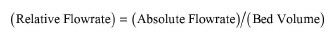
In terms of total eluant volume (per batch cycle and equipment unit), you can either set an absolute volume or a relative volume (in bed volumes). The buffer’s absolute volume is equal to its relative volume times the resin’s volume. This relation is used to determine the absolute volume based on a relative volume, and vice versa.
The process time can be either set by user or calculated based on the total eluant volume and absolute total eluant flowrate as follows:
|
|
where ‘Feed Volume’ denotes the total eluant volume in the context of this operation. If the process time is set by user then the above equation is used to calculate the total eluant flowrate.
In terms of total eluant flowrate, if the process time is not set, you can specify any one of the following three variables: linear velocity, absolute flowrate, or relative flowrate. The other two variables will be calculated by the program according to the following equations:
|
|
|
|
If the process time is set, the above two equations are used to calculate the linear velocity and relative flowrate, respectively.
For isocratic elution, a single buffer (eluant A) is used, having a volume equal to the total eluant volume.
For gradient elution, the gradient buffer is generated by mixing two different buffers in continuously varying ratios. In that case, you need to identify the two buffer (eluant) streams (A and B) and specify either the initial and final concentrations of a “key component” in the gradient buffer, or the initial and final volumes of buffer “A” in the gradient buffer. Based on these, the program will calculate the volumes of the two buffers.
When the gradient elution is based on key component data, the concentration of the key component is assumed to vary linearly with buffer volume, as shown in the figure below:
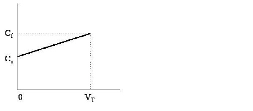
In the above figure, Co and Cf are the respective initial and final concentrations of the key component (in mol/L) and VT is the gradient elution buffer. To estimate the volumes of buffers A and B that are mixed to form the gradient elution buffer, we do the following simple material balances:
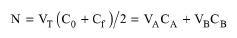
The total number of moles, N, of the key component contained in the gradient buffer of volume VT is given by:
|
|
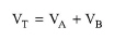
where VA, VB are the volumes of buffers A and B, respectively, required to form the gradient buffer of volume VT. CA and CB are the concentrations of the key component in buffers A and B, respectively. Also VT
|
|
is equal to:
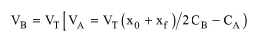
The above equations are solved for VA and VB and the answer for VB is given below:
|
|
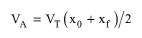
Similarly, when the gradient elution is based on the initial (xo) and final (xf) volume fractions of buffer A in the gradient buffer, the volume fraction of buffer A in the gradient buffer is assumed to vary linearly with the gradient buffer’s volume. Then, the volume of buffer A in the gradient buffer is given by:
|
|
The calculated buffer volumes are used to adjust the flowrates of the corresponding streams. If the streams have source unit procedures (e.g., buffer preparation tanks), the flowrate adjustment is recursively back-propagated till process feed streams are reached. At least one of the process feed streams that feed into elution or regeneration-equilibration-wash streams must have non-zero flowrate.
The ‘Eluant Volume in Collection Stream’ factor (in membrane volumes) determines the fraction of an elution buffer that ends up in the collection stream. The remaining exits in the waste stream. For each component, a percentage of the corresponding retained amount in the membrane equal to the specified release % for that component is also removed from the membrane and added to the collection stream.
The interface of this operation has the following tabs:
● Oper. Cond’s, see Column Elution: Oper. Conds Tab
● Elution Strategy, see Column Elution: Elution Strategy Tab
● Labor, etc, see Operations Dialog: Labor etc. Tab
● Description, see Operations Dialog: Description Tab
● Batch Sheet, see Operations Dialog: Batch Sheet Tab
● Scheduling, see Operations Dialog: Scheduling Tab