This tab is part of the Auxiliary Equipment Properties Dialog that is displayed for auxiliary equipment of the “Transfer Panel” type. This dialog can be accessed by clicking on the View/Edit button ( ) from the Process Explorer Toolbar (Aux. Equipment tab) or on the Auxiliary Equipment Listing showing when selecting Tasks } Other Resources } Auxiliary Equipment... from the main menu of the application.
The following table shows the meaning of the variables appearing in this tab, as well as their default values and their generally acceptable range. Note that due to the manner by which the variables are used by the sizing and costing equations, the range of acceptable values may be further reduced.
|
Variable |
Default Value |
Range |
|
|
||
|
○ Name |
TP-101 |
Any Text |
|
● Type |
Transfer Panel |
Any Text |
|
○ Maximum Number of Parallel Engagements (Number of Bridges) |
1 |
Positive |
|
◙ Number of Units |
1 |
Positive |
|
● Size Variable Description |
Volumetric Flow |
Any Text |
|
◙ Maximum Throughput |
1000.0 L/h |
Positive |
|
◙ Volumetric Flow |
0.0 |
Positive |
Symbol Key: ○ User-specified value (always input); ● Calculated value (always output); ◙ Sometimes input, sometimes output
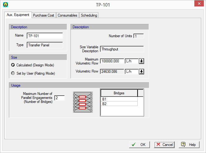
The following list describes the available specification choices in this tab; for more details on how these are implemented, see Vacuum Pumps.
In Calculate (Design Mode), the user specifies the Maximum Volumetric Flow and the program calculates the Number of Units and Volumetric Flow (based on the actual engagements by the operations that utilize this unit).
In User-Defined (Rating Mode), the user specifies the Number of Units and (rated) Volumetric Flow. The program simply displays a warning if the required volumetric flow per unit (based on utilization possibly synchronous by several operations) exceeds the specified (rated) Volumetric Flow of the panel.