 button is pressed on the main toolbar).
A unit procedure (aka a procedure) in the context of a SuperPro Designer simulation is defined as a sequence of actions representing the most elementary physico-chemical transformations supported by the software all assumed to take place inside the same equipment resource. Each such action is represented by a unit operation as described in more detail in What Is a Unit Operation?
► To Add a New Unit Procedure...
2. Make sure you are in select mode (the button is pressed on the main toolbar).
a) Select the unit procedure’s type from the Unit Procedures submenu. Notice that the mouse pointer will change to: : The ‘Add Unit Procedure’ mouse pointer.
c) Click in an unoccupied area of the flowsheet. The unit procedure’s icon will be inserted such that its center coincides with your last mouse click.
If you move your mouse pointer over a procedure it will turn into:
 : The ‘Command Menu’ (or ‘Context Menu’) mouse pointer
indicating that if you right-clicked over that procedure’s icon, you will be presented with a menu of commands. This menu is called the procedure’s command menu (or context) menu; sometimes, we simply call it the right-click menu. The menu includes commands that can be issued to the procedure that is currently selected.
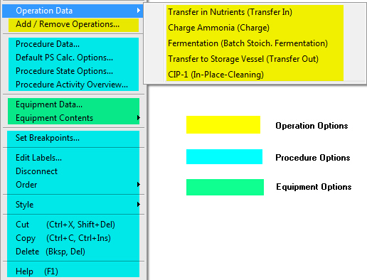
Command (context) menu for a unit procedure.
Please note that the contents of the menu do not depend on the unit procedure type (Chromatography, Filtration, etc.).
When modeling a batch process (also mentioned as a batch recipe) you may think of a batch unit procedure as simply a set of sequential operations; for example: ‘Charge A’, ‘Charge B’, ‘Heat’, ‘Stir’, ‘React’, ‘Transfer Out’. A unit procedure may include any number of operations. Even though the operations are listed sequentially, they may be timed to occur concurrently. For example, you may specify to have operation ‘Stir’ execute continuously while ‘Charge A’, Charge B’ and ‘React’ are set to execute concurrently (see The Scheduling Tab).
A unit procedure typically engages some kind of main equipment resource (Reactor, Fermentor, Diafilter, Nutche filter, etc.). In batch processing, two or more unit procedures can share the same main equipment resource. However, you must make sure that they are scheduled to execute in such a way that their equipment resource occupation times do not overlap. If this happens inadvertently, the program will generate an error message during simulation notifying the user that an equipment sharing violation has been detected.
The types of operations that can be included in a unit procedure depend on the type of equipment resource (Reactor, Diafilter etc.) hosting the procedure and the operating mode of the unit procedure (batch or continuous).
|
|
Once a given procedure type is selected (from the list under the main menu Unit Procedures) then the equipment type assumed as a host is automatically selected. For example, if you select to include a gel filtration procedure, the equipment resource assumed as a host is always a GFL chromatography column. If there could be different hosts for the same procedure, then a separate entry in the Unit Procedures menu will be present. For example, there could be any one of several different host equipment for a batch vessel procedure: a stirred tank reactor, a fermentor, a seed fermentor, etc. For each supported equipment host a distinct entry exists under the Unit Procedures } Batch Vessel Procedure menu option. |
When modeling a continuous process (e.g., a typical wastewater treatment plant), you may think of a (continuous) unit procedure as simply a single unit operation: a CSTR or an aeration basin simply represents a container vessel that receives flow continuously, processes (reacts) continuously and outputs flow continuously. Since the (single) operation represented by the unit procedure is active (‘on’) all the time, a continuous unit procedure cannot share its equipment resource.
Each unit procedure is represented on the flowsheet by an equipment-looking icon. There may be one or more input streams attached to the unit procedure as well as one or more output streams leaving the unit procedure. Every unit procedure is assigned a main equipment resource of the type that is required for that procedure type. However, as mentioned in A Unit Procedure in a Batch Process, in the case of batch processes, more than one unit procedures (of the same type) can be set to use the same equipment resource.
|
|
Even though you may be tempted to treat each icon shown on a flowsheet as representing equipment, you shouldn’t unless the process (and all unit procedures) are in continuous mode. In batch mode, always think of each icon as representing a set of actions executed in an equipment resource of the type indicative by the appearance of the icon. There may be one, several or no actual equipment behind a processing step represented by an icon on the flowsheet. |
Under a unit procedure icon you can see two labels displaying three name tags. The first label (name label) displays a string that is made up from three parts:
the name of the unit procedure,
a name-separator (defaults to a ‘/’ character) and
the name of the hosting equipment resource.
The second label (description label) is shown as a separate line and displays a short description of the unit procedure. Sometimes there will be some other small indicator bitmaps
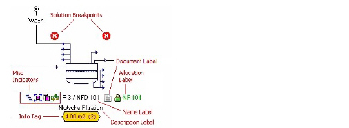
Labels and indicator bitmaps shown around a unit procedure icon.
appearing across the top or the across the bottom of the procedure’s icon. All bitmap indicators that may appear across the top of the icon are related to the presence of breakpoints (see Simulation Breakpoints). Occasionally, when the simulation is paused by the presence of a breakpoint, there may be more bitmap indicators showing under the procedure icon. Those bitmaps indicate the solution state of the procedure (for more details, see Simulation Breakpoints). Finally, some other small bitmap indicators may appear at the bottom left or bottom right of a procedure’s icon. These bitmaps may remind the user of certain special circumstances surrounding the function of the procedure (e.g. multiple cycles or multiple equipment units, etc.).
Please note that the general appearance of a procedure's icon (including its labels and presence or absence of bitmap indicators around the icon) is determined by its drawing style. For more details on the meaning of each bitmap indicator and how to turn them on or off, see Unit Procedure Icon Style.

