This operation is used to simulate the generation of electric power by combustion of fuel and air in a reciprocating internal combustion engine coupled to an electric generator.
● Power Generation in an IC-Engine-Generator Procedure
Fuel and air are fed into the hosting equipment continuously through the designated input ports for the fuel and air streams, respectively. The fuel stream is used to carry combustible gaseous or liquid fuels (e.g., natural gas, biogas, landfill gas, Diesel, etc.) and the air stream is used to carry the oxygen for combustion. The exhaust gas is transferred out continuously using the available output port.
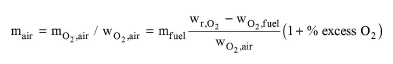
The flow of the air stream is always adjusted to match the specified percent excess oxygen of the air-fuel mixture or the specified air-fuel ratio. If the percent excess oxygen is specified, the mass flow rate of the air stream is calculated as:
|
|
where mair is the mass flow rate of the air stream, mO2,air is the stoichiometric mass flow rate of oxygen in the air stream, wO2,air is the mass fraction of oxygen in the air stream, mfuel is the mass flow rate of the fuel stream, wr,O2 is the theoretical mass of oxygen required for complete combustion of the fuel stream per unit mass of fuel stream, and wO2,fuel is the available mass of oxygen in the fuel stream (which is the sum of total fuel elemental oxygen and fuel stream oxygen) per unit mass of fuel stream. The calculation of wr,O2 and mO2,air is described in the section that describes the mass balances of combustion reactions.
The relative humidity of air is calculated by dividing the partial pressure of water vapor in the air stream by the saturation pressure of water vapor at the specified air stream temperature. The partial pressure of water vapor in the air stream is calculated by multiplying the pressure of the air stream by the mol fraction of water vapor in the air stream. The saturation pressure of water vapor at the specified air stream temperature is calculated from the saturated vapor pressure (Antoine) correlation for the pure component which is associated with water through the Fuel-Air Combustion: Components Tab.
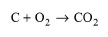
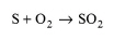
The model considers the complete combustion of combustible fuel elements C, H and S into carbon dioxide, water vapor and sulfur dioxide, respectively, in the presence of stoichiometric or excess oxygen. For each pure component of the fuel stream that is identified by the user as a combustible fuel, its elemental C, H, O, N and S composition must be specified (see Fuel-Air Combustion: Fuel Tab). If the fuel contains additional elements, then these may be added to the composition of elemental N. Any molecule present in the combustion gas (i.e., carbon dioxide, water, sulfur dioxide, oxygen) must be associated explicitly with a registered pure component (see Fuel-Air Combustion: Components Tab).
The elemental oxygen contained in the fuel is assumed to participate in combustion reactions with C, H and S. The elemental nitrogen contained in the fuel is taken to appear as gaseous nitrogen in the combustion products. The reaction of nitrogen contained in the air with oxygen and hydrocarbons is not considered. Only the following combustion reactions are considered:
|
|
|
|
|
|
From the stoichiometry of the above reactions, the moles of combustion gases CO2, H2O and SO2 produced per mole of fuel component i from the complete combustion of that component are calculated as:
|
|
|
|
|
|
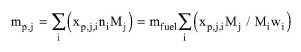
where xC,i, xH2,i and xS,i are the respective moles of elemental carbon, elemental hydrogen and elemental sulfur per mole of fuel component i. The total mass flow rate of combustion gas j (j=CO2, H2O, or SO2) produced by complete combustion of all combustible fuel components can be calculated as:
|
|
where Mj is the molecular weight of combustion gas j, ni is the mole flow of fuel component i, Mi is the molecular weight of fuel component i, and wi is the mass fraction of fuel component i.
The theoretical moles of oxygen required for the complete combustion of fuel component i per mole of that fuel component can be calculated as:
|
|
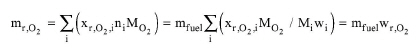
Then, the total mass flow rate of theoretical oxygen required for the complete combustion of all fuel components can be calculated as:
|
|
where wr,O2 is the theoretical mass of oxygen required for complete combustion of the fuel per unit mass of fuel. The stoichiometric air-fuel ratio displayed on the interface of this operation can then be calculated by dividing mr,O2 by the mass flow rate of the fuel stream.
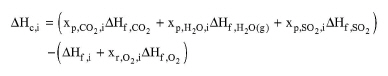
From the stoichiometry of the combustion reactions, the molar heat of combustion of each fuel component is calculated as:
|
|
where ΔHf is the molar enthalpy of formation of each molecule. This is calculated as:
|
|
where:
● ΔH0f is the standard enthalpy of formation of the molecule,
● Cp is the mean specific heat capacity of the molecule,
● T0 is the temperature at which the standard enthalpies of formation are given (25 oC), and
● T is the reference temperature used for enthalpy calculations by the program.
The lower heating value (LHV) of each fuel component corresponds to the negative value of the standard enthalpy of combustion (LHVi=-ΔΗoc,i). This can be calculated from eq. (A.398), if ΔHf is substituted by ΔHof for all molecules.
The standard enthalpies of formation of fuel components and of pure component associated with combustion products (CO2, H2O, SO2, and O2) are taken from the program’s pure component database. The standard enthalpy of formation of the “Water” component included in the Designer database (-285.83 kJ/mol) corresponds to liquid water. In a similar manner, the standard enthalpy of formation of the pure component that is associated with H2O is assumed to correspond to liquid water. This is converted into standard enthalpy of formation of water vapor, as follows:
|
|
where ΔH0v is the latent heat of vaporization of water at 25 oC (which is assumed equal to 44 kJ/mol).
The total heat of combustion of the fuel stream expressed in units of energy per unit mass of fuel stream is calculated as:
|
|
where xi is the mass fraction of fuel component i in the fuel stream.
The total heat input in the combustion chamber expressed in units of energy per unit mass of fuel stream can be calculated as:
|
|
where ΔHfuel is the specific enthalpy of the fuel stream and ΔHair is the specific enthalpy of the air stream.
The energy balance around the engine is this:
Total Heat Input = Exhaust Gas Enthalpy + Heat Losses + Heat Dissipation + Mechanical Power Output.
The exhaust gas enthalpy is calculated based on the specified exhaust gas temperature and pressure. The heat losses to the surroundings are calculated by multiplying the fuel heat input (based on LHV) by the specified heat loss %. The fuel heat input (based on LHV) is calculated by multiplying the LHV of each fuel component by its mass flow rate. The mechanical power output is calculated by multiplying the fuel heat input (based on LHV) by the specified thermal efficiency of the engine (which is defined as the ratio of the mechanical power output of the engine to the fuel heat input based on LHV).
The program solves the above energy balance in order to calculate the heat dissipation. This is the heat that is rejected to the cooling agent and/or recovered by the cold water stream. If heat recovery is not considered, then the cooling duty is the same as the heat dissipation.
If heat recovery is considered, then some heat may be recovered by a cold water stream in order to produce hot water. In that case, the heat recovery is calculated by multiplying the heat dissipation by the specified heat recovery %. Also, any heat that is not recovered, is rejected to the cooling agent (i.e., the cooling duty is equal to heat dissipation minus heat recovery). Subsequently, the enthalpy of hot water can be calculated to be the sum of cold water enthalpy and heat recovery. Also, the mass flowrate of hot water can be calculated by dividing the enthalpy of hot water by its specific enthalpy (which is calculated based on the specified hot water temperature).
The electric power produced by the electric generator which is coupled to the IC engine can be calculated by dividing the mechanical power output of the IC engine by the specified generator efficiency.
The electrical efficiency of the IC engine-generator is defined as the ratio of the electrical power output of the engine-generator to the thermal energy input of the fuel (based on LHV).
In Design mode, the user specifies the maximum (electric) power output of the IC engine-generator. If the operating power exceeds the maximum power, the program assumes multiple units operating in parallel with a total power equal to the calculated power.
If the equipment size option is in Rating Mode, the user specifies the rated (electric) power and the number of units. If the calculated power per unit exceeds the rated power, a warning is displayed advising the user to increase the rated power or the number of units.
1. Niessen, W. R., Combustion and Incineration Processes, Third Edition, Marcel Dekker, Inc., 2002.
2. Darrow K., Tidball R., Wang J. and Hampson A., Catalog of CHP Technologies, Section 2. Technology Characterization - Reciprocating Internal Combustion Engines, EPA CHP Partnership, March 2015.
3. Petchers N., Combined Heating, Cooling & Power Handbook, Technologies and Applications, The Fairmont Press, Inc., Marcel Dekker, Inc., 2002.
4. Rutherford J., Heat and Power Applications of Advanced Biomass Gasifiers in New Zealand’s Wood Industry, Thesis Submitted in Fulfillment of the Requirements for the Degree of Master of Engineering in Chemical and Process Engineering, University of Canterbury, 2006.
The interface of this operation has the following tabs:
● Oper. Cond’s, see Power Generation in an IC Engine-Generator: Oper. Conds Tab
● Fuel, see Fuel-Air Combustion: Fuel Tab
● Components, see Fuel-Air Combustion: Components Tab
● Labor, etc, see Operations Dialog: Labor etc. Tab
● Description, see Operations Dialog: Description Tab
● Batch Sheet, see Operations Dialog: Batch Sheet Tab
● Scheduling, see Operations Dialog: Scheduling Tab