The following table shows a brief description of the variables appearing in this tab. The table also displays their default values and their generally acceptable range.
|
Variable |
Default Value |
Range |
|
|
||
|
○ Air Stream |
<None> |
Designated Air Stream |
|
◙ Excess Oxygen (%) |
80.0 |
Positive |
|
◙ Air-Fuel Ratio |
0.0 |
Positive |
|
● Stoichiometric Air-Fuel Ratio |
0.0 |
Positive |
|
● Air Throughput per Unit |
0.0 |
Positive |
|
● Heat Input (LHV) (kW) |
0.0 |
Positive |
|
○ Heat Losses (%) |
5.0 |
0-100 |
|
○ Exhaust Gas Temperature (oC) |
400.0 |
0-100 |
|
○ Exhaust Gas Pressure (bar) |
1.013 |
Positive |
|
● Heat Dissipation (kW) |
0.0 |
Positive |
|
● Cooling Duty (kW) |
0.0 |
Positive |
|
○ Cooling Agent Name |
<Chilled Water> |
Any Cooling Agent |
|
● Inlet Temp. (oC) |
5.0 |
Positive |
|
● Outlet Temp. (oC) |
10.0 |
Positive |
|
● Rate (kg/h) |
0.0 |
Positive |
|
○ Heat Transfer Effic. (%) |
100.0 |
(0,100) |
|
○ Cold Water Stream |
<None> |
Designated Cold Water Stream |
|
○ Include Heat Recovery? |
No |
Yes/No |
|
○ Heat Recovery (%) |
100.0 |
0-100 |
|
○ Hot Water Temp. (oC) |
80.0 |
Positive |
|
○ Power Type |
<Std Power> |
Any Power Type |
|
○ Thermal Efficiency (%) |
0.0 |
0-100 |
|
● Mechanical Power (kW) |
0.0 |
Positive |
|
○ Generator Efficiency (%) |
96.0 |
0-100 |
|
● Electric Power |
0.0 |
Positive |
|
● Electrical Efficiency (%) |
0.0 |
0-100 |
|
○ Setup Time |
0.0 |
Positive |
|
◙ Process Time (min) |
60.0 |
Positive |
|
○ Ignore Labor? |
Yes |
Yes/No |
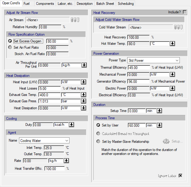
Symbol Key: ○ User-specified value (always input); ● Calculated value (always output); ◙ Sometimes input, sometimes output
The following list describes the available specification choices in this tab; for more details on how these are implemented, see Power Generation in an IC Engine-Generator: Modeling Calculations.
•Air flow specification options...
You may choose to either specify the percent excess oxygen of the air stream or the air-fuel ratio.
•Heat Recovery/Cooling Duty...
By default, the “Include” heat recovery option is not checked, and the entire heat that must be dissipated is transferred to the cooling agent. If the above option is checked, then you must specify the percent of total heat dissipation that is recovered by a cold water stream (turning it into hot water) and the temperature of the hot water that is produced. If the specified percentage is less than 100%, then the remaining percentage is assumed to be transferred to the cooling agent.
•Duration options...
Duration options are only available in batch mode. You can set the process time, or have the process time calculated based on air throughput, or match the duration of this operation to the duration of another operation by introducing a master-slave relationship between the two operations. If you introduce a master-slave relationship, the program will match the setup time, the process time and the turnaround time of this operation (the ‘slave’) with the corresponding times of the reference operation (the ‘master’ operation). For more details on how to setup a master-slave relationship, see The Scheduling Tab.