This unit operation can be used to simulate anaerobic digestion when the reaction stoichiometry and kinetics are known.
Anaerobic digestion is one of the oldest processes used for the stabilization of sludges. It involves the decomposition of organic and inorganic matter in the absence of molecular oxygen. The major applications have been, and remain today, in the stabilization of concentrated sludges produced from the treatment of wastewater and in the treatment of some industrial wastes. More recently, it has been demonstrated that dilute organic wastes can also be treated anaerobically (Tchobanoglous and Burton, 1991).
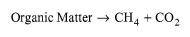
Anaerobic digestion utilizes airtight tanks in which anaerobic microorganisms stabilize the organic matter producing methane, carbon dioxide and other end products:
|
|
Roughly four groups of microorganisms sequentially degrade organic matter. Hydrolytic microorganisms degrade polymer-type material such as polysaccharides and proteins to monomers. The monomers are then converted into fatty acids with a small amount of H2. The principal acids are acetic, propionic, and butyric with small quantities of valeric. All acids higher than acetic acid are converted into acetate and H2, by acetogenic microorganisms. The acetic acid and H2 are converted to CH4 by methanogenic organisms (Eckenfelder, 1989).
There are two main types of anaerobic digesters, standard rate and high rate. In the standard-rate digestion process, the digester contents are usually unheated and unmixed. The digestion period may vary from 30-60 days. In a high-rate digestion process, the digester contents are heated and completely mixed. The required detention period is 10-20 days.
The digester gas contains approximately 60-70% methane, 25-30% carbon dioxide and small amounts of hydrogen, nitrogen, hydrogen sulfide, and other gases. The gas has a heating value of 21,000-25,000 kJ/m3.
The hot water or steam used to heat digesters is most commonly generated in a boiler fueled by digestion gas. Up to 80% of the gas heating value can be recovered in a boiler. Additional heating (if required) is provided by natural gas.
● Kinetic Anaerobic Digestion Procedure
The anaerobic digester is modeled as a well-mixed reactor with kinetics. Any number of reactions can be specified that represent various types of reactions. The stoichiometry of a reaction can be specified on a mass or molar basis while the reaction rate is specified by selecting appropriate expressions for the substrate term, the oxygen term, and the biomass term. You may either specify the reaction rate constant of each reaction at the actual operating temperature or at a reference temperature. If the rate constant is specified at a reference temperature, the parameter ‘Theta’ that affects the calculation of the rate constant at any temperature must be specified too.
The reaction rate initialization interface offers flexibility in specifying a great variety of kinetic expressions. If, for instance, an average overall reaction rate is available for a certain type of industrial waste, it can be specified as the value of K with the ‘None’ option selected for the substrate, oxygen, and biomass terms. Such overall reaction rate data are available for several industrial wastes (Eckenfelder, 1989, pp. 249, 256).
For sludge stabilization, the values of rate constants are usually in the following ranges:
● K = 0.010 - 0.020 1/h (for hydrolytic and catabolic reactions)
● KS = 8,000 - 12,000 mg/L (for hydrolytic and catabolic reactions)
● KD = 5x10⁴ - 7x10⁴ 1/h (for active biomass decay reactions)
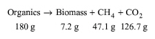
The yield coefficient, Y [g biomass / g substrate] is usually in the range of 0.04 - 0.06. This information is useful in specifying the stoichiometry of a degradation reaction. An example of such a reaction follows:
|
|
eq. (A.76) |
Specify the ‘Gas Release %’ to account for gaseous components exiting in the gas outlet stream. Similarly, the ‘Sorption %’ determines the percentage of a component that adsorbs on the primary biomass component. The program, then, keeps track of the fraction in solution throughout the process with the ‘Extra-Cell %’ term. The ‘Extra-Cell %’ term represents the percentage of a component that is in solution while 100 - Extra-Cell% represents the adsorbed portion of a component.
Use the ‘Heating Agent’ variable to specify the utility used (e.g., natural gas, steam, etc.) for heating up the unit in the case of a high-rate digester.
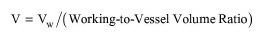
In Design Mode of calculation, the user specifies the residence time (tR) and the working to vessel volume ratio. The working (liquid) volume (Vw) and the vessel volume (V) are calculated using the following equations:
|
|
|
|
where F is the feed volumetric flowrate. If the calculated vessel volume exceeds its maximum possible value (specified through the Equipment tab), the program assumes multiple, identical units operating in parallel with a total vessel volume equal to the calculated. The tank depth is always specified by the user. Then, using the Length/Width ratio, the program calculates all the dimensions of the tank(s).
In Rating Mode, the user specifies the vessel volume and the working to vessel volume ratio and the program calculates the hydraulic residence time.
1. Eckenfelder, W.W., Jr., 1989, Industrial Water Pollution Control, McGraw-Hill, NY.
2. Tchobanoglous G. and F.L. Burton (1991). “Wastewater Engineering: Treatment, Disposal, and Reuse”, Third edition, Metcalf & Eddy, Inc., McGraw-Hill, Sec. 6-8.
3. Qasim S. R. (1994). “Wastewater Treatment Plants: Planning, Design and Operation”, Technonomic Publishing Co., Inc., Basel, Switzerland
The interface of this operation has the following tabs:
● Oper. Cond’s, see Anoxic Reaction Operations: Oper. Conds Tab
● Volumes, see Continuous Vessel Operations (Design Mode): Volumes Tab and Continuous Vessel Operations (Rating Mode): Volumes Tab
● Reactions, see Environmental Reaction Kinetics Dialog
● Gas Release, see Anoxic Reaction Operations: Gas Release Tab
● Sorption, see Environmental Reaction Operations: Sorption Tab
● Labor, etc, see Operations Dialog: Labor etc. Tab
● Description, see Operations Dialog: Description Tab
● Batch Sheet, see Operations Dialog: Batch Sheet Tab
● Scheduling, see Operations Dialog: Scheduling Tab