The main objective of this operation is to estimate the time for loading a column (if not specified by the user) and estimate the number and size of columns required (when the equipment is in Design Mode). The same operation handles loading of cation exchange, anion exchange, and mixed bed columns.
● Ion Exchange Procedure (for Demineralization)
The specified binding fraction for each component of the feed stream is used to determine the total fraction of ions that bind to the resin. The remaining fraction of ions that do not bind to the resin exit through the outlet stream.
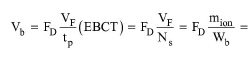
In Design Mode, the following equations are used for the calculation of the operation’s total bed volume requirement and breakthrough time based on the specified service volume (expressed as number of bed volumes), binding capacity (expressed as either CaCO3 or ion mass), or ion exchange capacity:
|
|
where:
● FD is the equipment’s overdesign factor,
● VF is the total feed volume per procedure cycle,
● tp is breakthrough (process) time,
● EBCT is the empty-bed contact time,
● Ns is the service volume (expressed as number of bed volumes),
● mion is the total mass of ions that bind to the resin(s) per procedure cycle,
● Wb is the resin binding capacity (expressed as mass of ions per bed volume).
● x is the total amount of ions expressed in equivalents per procedure cycle, and
● Cb is the resin’s ion exchange capacity (expressed as equivalents per unit bed volume),
In Rating Mode, the value of FD in the above equation is taken to be 1. The value of EBCT is usually in the range of 1.5 to 7.5 min (Clifford, 1990).
For a description of binding capacity, see the “Binding Capacity” section below. For a description of ion exchange capacity, see the “Ion Exchange Capacity” section below.
Two options are available for column sizing:
a) Set Resin Capacity
b) Set Service Volume
If the “Set Resin Capacity” option is selected, the user may specify either the resin’s binding capacity (expressed as either CaCO3 or ion mass) or ion exchange capacity. The program will first calculate the bed volume based on the specified resin capacity, and then it will calculate the service volume based on the calculated bed volume: If the “Set Service Volume” option is selected, the program will first calculate the bed volume based on the specified service volume, and then it will calculate the resin’s binding and ion exchange capacities based on the calculated bed volume:
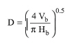
Dividing the bed volume by the ‘Bed to Column Height’ ratio yields the column volume. When the bed height, Hb, is specified, its diameter, D, is calculated using the following equation:
|
|
If D > Dmax, then multiple columns are assumed in parallel. Alternatively, the user may specify the ‘Bed Height to Diameter’ ratio and have the model calculate the bed and column dimensions.
If the Plant Operation Mode is Batch, the feed volume per cycle (VF) is calculated by dividing the corresponding feed volume per batch by the procedure’s Number of Cycles per Batch. Similarly, a pure component’s mass per batch is converted into mass per cycle by multiplying by the Number of Cycles per Batch. A component’s bound mass per cycle is calculated by multiplying the corresponding feed mass per cycle by the corresponding binding percentage. The total bound mass per cycle (mion) is calculated as the sum of bound masses over all components that are not ‘Ignored in Sizing’.
If the Plant Operation Mode is Continuous, VF is calculated by multiplying the volumetric flow rate of the feed stream by the procedure’s Holdup Time. Similarly, mion is calculated by multiplying the total mass flow rate of bound components by the procedure’s Holdup Time. The total mass flow rate of bound components is calculated by summing up the binding mass flow rates of those components whose ‘Ignore in Sizing?’ check-box is not checked. A component’s binding mass flow rate is calculated by multiplying the corresponding mass flow rate in the feed stream by the corresponding binding percentage.
Note that the specified holdup time must be greater than or equal to the procedure’s Cycle Time divided by 1 + M, where M is the number of extra sets of equipment units in stagger mode; for more details on the use of holdup time, see Holdup Time; for more details on the use of stagger mode, see Staggered Mode.
The binding capacity of the resin refers to all the compounds that bind to the resin and whose ‘Ignore in Sizing?’ check-box is not selected. The binding capacity can be specified based on:
● Ion Mass, or
● CaCO3 hardness.
If the resin binding capacity is specified based on CaCO3, then, the ion mass flow refers to equivalent CaCO3. The CaCO3 ratio can be specified for a pure component through the ‘Aqueous’ tab of the Pure Components Properties page; for more details on viewing/editing the properties of a pure component, see Pure Component Properties. Please refer to the literature for a straightforward explanation of water hardness expressed on the basis of CaCO3 (Kemmer, 1988 – Chapter 4).
In Design Mode, as well as in Rating Mode, the program will check that the specified binding capacity is adequate for retaining the specified binding fractions of all feed stream components that are not ‘ignored in sizing’.
In order to size a column based on ion exchange capacity, the user must do the following:
1. Add components to represent ions (e.g., “Na+”, “Ca++”, “Cl-”, “SO4--”) and specify the oxidation state of those components (ions) through the Pure Component Properties dialog (see Pure Component Properties Dialog: IDs tab) (e.g., 1 for “Na+”, 2 for “Ca++”, -1 for “Cl-”, -2 for “SO4--”). The oxidation state of an ion (atom) is the number of electrons gained or lost in order to form a chemical bond with another ion (atom). A positive oxidation state indicates a cation, a negative oxidation state indicates an anion, and zero oxidation state indicates a non-ionic component (a molecule).
2. Add a GBX reaction/separation procedure before the INX procedure to simulate the dissociation reactions of salts contained in the feed stream (e.g., “NaCl” --> “Na+” + “Cl-“).
3. Choose the “Ion Exchange Capacity” option and specify the resin’s ion exchange capacity in equivalents per unit volume (by default, eq/L). Equivalents are a measure of the ion exchange sites taken up by the loaded ions. For each adsorbed ion, the equivalents can be calculated by multiplying the adsorbed moles by the ion’s valence. For example, if 0.9 mol of Ca++ ions are adsorbed, then the number of Ca++ equivalents is 1.8 since the valence of Ca++ ions is 2. If the ion exchange capacity of the cation resin is 1.8 eq/L, then the volume of resin required in order to adsorb 1.8 eq of Ca++ ions is 1 L (1.8 eq divided by 1.8 eq/L).
4. Choose a “Resin Type” (“Cation” or “Anion”). A cation resin can adsorb cations, whereas an anion resin can adsorb acids. The ion exchange capacity of a cation resin is expressed in equivalents per unit volume of cations, whereas the ion exchange capacity of an anion resin is expressed in equivalents per unit volume of anions. If a cation resin is selected, the title of the “Valence” column of the pure components table will change into “Cation Valence”, and that column will display only the valence of those pure components that represent cations (i.e., pure components whose oxidation state property is a positive number). For all other components, the displayed valence valence will be zero. If an anion resin is selected, the title of the “Valence” column of the pure components table will change into “Anion Valence”, and that column will display only the valence of those pure components that represent anions (i.e. pure components whose oxidation state property is a negative number). For all other components, the displayed valence value will be zero. A component’s valence corresponds to the absolute value of oxidation state of that component.
In design mode, for each pure component, the program will do the following:
● Calculate the adsorbed mass per cycle by multiplying the feed mass per cycle by the component’s binding capacity.
● Convert the adsorbed mass per cycle into adsorbed equivalents per cycle by multiplying with the component’s valence.
● Sum up the equivalents per cycle of all adsorbed ions in order to calculate the total equivalents of adsorbed ions per cycle.
● Divide the total equivalents per cycle by the specified ion exchange capacity in order to determine the total bed volume requirement.
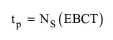
The breakthrough time corresponds to the process loading time. It can be either set by the user or calculated based on the specified EBCT. The following equation may be derived from eq. (A.186) for the calculation of breakthrough time from the empty-bed contact time and service volume:
|
|
If the breakthrough time is set by the user, then the above equation is used to calculate the EBCT. If the breakthrough time is calculated based on the EBCT, then the above equation is used to calculate the breakthrough time.
1. Clifford, D.A. (1990). Ion Exchange and Inorganic Adsorption. in “Water Quality and Treatment”, American Water Works Association, 4th Edition, McGraw-Hill, Inc., Edited by: F. W. Pontius.
2. Kemmer, F.N. (1988). The NALCO Water Handbook, 2nd Edition, McGraw-Hill Book Company.
● The feed stream must carry material of non-zero flow and of liquid/solid phase. If the material is found to be of mixed phase, then only the liquid/solid portion is considered in column size calculations.
● The total volume-specific mass of ions that bind to the resin per cycle must not exceed the binding capacity of the resin.
The interface of this operation has the following tabs:
● Oper. Cond’s, see INX Column Loading: Oper. Conds Tab
● Labor, etc, see Operations Dialog: Labor etc. Tab
● Description, see Operations Dialog: Description Tab
● Batch Sheet, see Operations Dialog: Batch Sheet Tab
● Scheduling, see Operations Dialog: Scheduling Tab