In diafiltration, water or some other solvent or buffer is added to the retentate to facilitate the removal of membrane-permeating species along with the water (or other solvent) during filtration. The addition of water (or other solvent) can be conducted under either one of two modes: discontinuous or continuous (O'Sullivan et al., 1984; McGregor, 1986).
In discontinuous operation, permeable solutes are cleared from the retentate by volume reduction (batch concentration), followed by re-dilution with water (or other solvent) and re-concentration in repetitive steps.
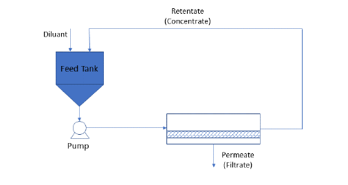
In continuous operation, water (or other solvent) is added at the appropriate pH and temperature to the feed tank at the same rate as the permeate flux, thus keeping the feed volume constant during the entire process. Permeable solutes are removed at the same rate as the flux. This mode of diafiltration is particularly useful if the concentration of the retained solute is too high to permit effective discontinuous diafiltration operation for purification.
SuperPro Designer simulates a continuous (true) diafiltration that can be (optionally) followed or preceded by any number of batch concentration operations. In general, if the initial solution is dilute, a concentration step to reduce the volume of the processed material is usually needed before the actual diafiltration.
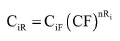
For the pre- and post- diafiltration batch concentration steps, the final concentration of a solute, i, in the retentate, CiR, is given by:
|
|
eq. (A.94) |
where CiF is the concentration of the solute in the feed, Ri is the rejection coefficient, n is the number of concentration stages, and CF is the concentration factor at each stage (see eq. (A.86)). The final mass fraction (fi) of component, i, in the retentate is equal to:
|
|
eq. (A.95) |
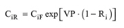
For the continuous diafiltration operation, the final concentration of a solute, i, in the retentate, CiR, is given by:
|
|
eq. (A.96) |
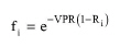
The mass fraction of a solute remaining in the retentate is calculated by the following equation:
|
|
eq. (A.97) |
where VPR is the volumetric permeation ratio, defined as follows:
|
|
where VS is the total volume of solvent added and VF is the initial feed volume.
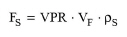
From eq. (A.98), the required mass flowrate of the diluant stream is calculated by:
|
|
eq. (A.99) |
where ρs is the density of the diluant stream.
Case where the diluant stream is not a feed stream. If the diluant stream of a diafilter has a source unit procedure, it must either be associated with a Pull Out operation in that procedure or the procedure must be able to back-propagate flow adjustments in its output stream(s). In the latter case, all input streams of the procedures that back-propagate flow adjustments must be set to ‘Auto-Adjust’ mode (by selecting the appropriate check box on the dialog windows of those input streams).
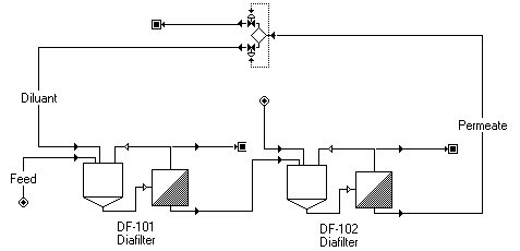
Case where the diluant stream is part of a recycle loop. If the diluant stream of a diafilter is part of a recycle loop (see figure below), it must be associated with a Pull Out or equivalent operation. Pull Out operations are available in Vessel procedures. The Custom Flow splitter (see figure below) can act as a Pull Out operation if the user selects one of the two bottom splitting specification options (e.g. Preserve Top Flow or Preserve Bottom Flow). For instance, in this case the option ‘Preserve Bottom Flow’ was selected. This allows the diafilter to draw the appropriate amount of diluant. The remainder of the recycled flow (Permeate stream) is directed to the top output stream of the custom flow splitter. If the Diluant flow demand is greater than the Permeate flow, then, the program generates an error message. Recycling of diafiltration buffer is practiced in certain product purification applications, such as blood fractionation.
The cost associated with the periodic replacement of membranes contributes to cost of Consumables. This cost is calculated based on the replacement frequency (in Operating Hours or Number of Cycles), the membrane unit cost (in $/m2), and the filtration time (specified by the user or calculated by the program).
The cost of electricity is estimated based on the Specific Power Requirement (in W/m2) that can be adjusted by the user. The heating or cooling duty and the associated costs are calculated based on the energy balance around the unit.
1. T. J. O'Sullivan, A. C. Epstein, S. R. Korchin, and N. C. Beaton (1984). Applications of Ultrafiltration in Biotechnology, CEP January.
2. W.C. McGregor (editor) (1986). Membrane Separations in Biotechnology, Marcel Dekker, Inc., New York and Basel.
The interface of this operation has the following tabs:
● Oper. Cond’s, see Diafiltration: Oper. Conds Tab
● Utilities, see Batch Concentration: Utilities Tab
● Labor, etc, see Operations Dialog: Labor etc. Tab
● Description, see Operations Dialog: Description Tab
● Batch Sheet, see Operations Dialog: Batch Sheet Tab
● Scheduling, see Operations Dialog: Scheduling Tab