eq. (A.60)
The Continuous Stoichiometric Reaction in an Electrowinning Cell model can be used to simulate a continuous electrowinning reaction that takes place in an Electrowinning Cell when the reaction kinetics are unknown (or unimportant) but the mass stoichiometry is known, and either the reaction’s conversion with respect to a particular reactant (e.g., limiting component) or the target concentration of a particular reaction product can be specified.
● Continuous Stoichiometric Reaction Procedure in an Electrowinning Cell
If the additives/feed ratio on mass basis is set, the mass flowrate of the additives stream is calculated by multiplying the mass flowrate of the feed stream by the specified additives/feed ratio on mass basis.
If the additives/feed ratio on volume basis is set, the mass flowrate of the additives stream is calculated by multiplying the volumetric flowrate of the feed stream by the specified additives/feed ratio on volume basis and by the density of the additives stream.
The operating pressure is assumed equal to the ambient pressure.
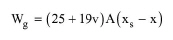
If the option to ignore the water evaporation is not checked, then the water evaporation percentage can be set by the user. Alternatively, in the case that the exit temperature is set, it can be calculated by the program based on an empirical model that calculates the evaporation rate of water from a water surface based on the water temperature, water-air surface area, air temperature, air humidity and air velocity. The evaporation rate of water is calculated using the following expression:
|
|
eq. (A.60) |
where
● Wg is the evaporation rate (in kg/h),
● v is the air velocity (in m/s),
● A is the water-air surface area (in m2),
● xs is the maximum humidity ratio of saturated air at the same temperature as the water surface (in kg water vapor/kg dry air), and
● x is the humidity ratio of air (in kg water vapor/kg dry air).
Notice that the units of the LHS and RHS don’t match since this is an empirical equation.
The water-air surface area, A, is equal to the electrode width times the cell length times the number of units.
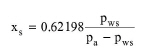
The maximum humidity ratio of saturated air at the same temperature as the water surface, xs, is calculated from the following equation:
|
|
eq. (A.61) |
where
● pws is the saturation pressure of water vapor in the air (in Pa), and
● pa is the air pressure (which is assumed equal to the ambient pressure) (in Pa).
The humidity ratio of air is calculated as follows:
|
|
eq. (A.62) |
where RH is the relative humidity of air.
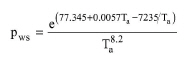
The saturation pressure of water vapor in the air is estimated from the following equation:
|
|
eq. (A.63) |
where Ta is the dry bulb temperature of moist air (in K).
The calculated evaporation rate of water, Wg, is then divided by the liquid/solid mass flow rate of water in the inlet mixture, Win, to calculate the evaporation fraction of water.
First, if the option to ignore the water evaporation is not checked, the program calculates the mass flow rate of evaporated water and the enthalpy change of water evaporation, then based on the specified or calculated water evaporation percentage. The mass flow rate of evaporated water is directed to the vent stream, and the remaining inlet mass flow rate is subsequently used to perform the material and energy balances for the reaction.
For the reaction, the user provides the mass or molar stoichiometric coefficients (Ai) of the various components and either the conversion based on a chosen reactant (either the limiting component or another conversion-reference component) or the target concentration of a chosen reaction product (the concentration-reference component) at the end of the reaction. The algorithm used by the program to perform the material balances for the reaction is described in the following paragraphs.
If the specified conversion is based on the limiting component then, first of all, the limiting component is identified. This is done based on the mass stoichiometry and on the composition of the reacting mixture. If the specified conversion is based on a conversion-reference component, then first of all, the program attempts to validate that the specified conversion is achievable (i.e., there are enough reactants for the reaction to proceed to such an extent). If that is not the case, then the program displays a warning and it uses the maximum achievable conversion of the conversion-reference component in subsequent calculation.
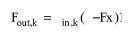
For the limiting component (k) or the conversion-reference component (depending on what is the case) the following holds:
|
|
where:
● Fout,k is the mass flowrate of the component after the reaction,
● Fin,k is the mass flowrate of the component before the reaction, and
● x is the conversion (either the specified one or the maximum achievable conversion).
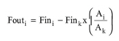
For any other component, the mass flow rate after the reaction can be calculated as follows:
|
|
where:
● Fout,i is the mass flowrate of component “i” after the reaction,
● Fin,i, Fin,k are the mass flowrates of components “i” and “k” (limiting component), respectively, and
● Ai, Ak are the stoichiometric coefficients of components “i” and “k” (limiting component), respectively.
After the material balance for the reaction is done, any gaseous reaction product component that is not set as a cathode or anode product, is directed to the vent stream. The liquid phase is split into cathode products (if any), anode products (if any) and spent electrolyte, based on which components are checked as recovered, and which recovered components are checked as cathode products (any components checked as recovered that are NOT checked as cathode products are assumed to be anode products).
The program then solves the overall energy balance to calculate either the exit temperature (in the case that the operation is adiabatic or the heating or cooling duty is set) or the heating or cooling duty (in the case that the exit temperature is set). The overall energy balance accounts for the enthalpy of the inlet mixture, the enthalpies of the outlet streams (vent, cathode products, anode products, and spent electrolyte), the heat of the reaction, the enthalpy change of vaporization of water, and the electric power losses that are converted into heat (see below).
Please note that in Design mode, if the water evaporation is not ignored, the material and energy balances and equipment sizing (see below) are solved iteratively because the water evaporation depends on the number of units and on the number of cathodes.
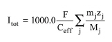
In Design mode, after solving the material and energy balances, the program calculates the total electric current required to achieve the desired conversion from the following equation, which is based on Faraday’s law:
|
|
where:
● Itot is the total electric current intensity (in Amperes)
● F is the Faraday constant (96,485 Coulomb/mol),
● Ceff is the current efficiency,
● mj is the mass flow rate of recovered product component “j” (in kg/s)
● zj is the source ion valency of product component “j”, and
● Mj is the molecular weight of product component “j” (in kg/kmol)
The number of electrons transferred (through the external wire) per mol of recovered product component is the number of electrons exchanged to produce one mol of that component. It can be determined by multiplying the number of ions used to form one mol of the product component by the valency of those ions. For example, if the product is copper, the source ion for the production of copper is Cu++. Since one Cu++ ion is used to form 1 mol of copper, and the valency of Cu++ is 2, the number of electrons transferred per mol of copper is 2.
The electrons transferred per molecule of product can be set either for cathode products or for anode products. In the case that the electrons transferred per molecule of product are set for the cathode products, then only the cathode product components are considered in the above calculation. In the case that the electrons transferred per molecule of product are set for the anode products, then only the anode product components are considered in the above calculation.
Subsequently, the calculated total electric current requirement is divided by the specified current density to determine the total active surface area requirement. Depending on whether the electrons transferred per molecule of product are set for the cathode products or for the anode products, the calculated total active surface area requirement is that of the cathodes or that of the anodes. If the electrons transferred per molecule of product are set for the anode products, the program will convert the total anode active surface area requirement into total cathode active surface area requirement. To do that, in the case that the selected electrode is an electrode pair, the program simply assumes that the total anode active surface area is the same as the total cathode active surface area. In the case that the selected electrode is either a cathode or an anode, the program first calculates the maximum number of anodes by adding the specified difference between the number of anodes and cathodes to the specified maximum number of cathodes. Then, based on the assumption that the anodes and cathodes have the same area, the program calculates the maximum anode surface area to be equal to the number of anodes times the electrode area. By dividing the total anode surface area requirement by the maximum anode surface area, the program calculates the number of units. Then, the total cathode surface area requirement is calculated by subtracting the product of electrode area times the difference between anodes and cathodes from the total anode surface area requirement.
After determining the total cathode surface area requirement, the program uses that value to size the equipment. In the case that the host equipment is shared by many procedures, the total cathode surface area requirement will be determined for each and every operation carried out as part of one of the unit procedures hosted by the equipment resource, and the software will size the cell based on the largest demand on total cathode surface area amongst all operations executed in the cell.
If the equipment does not operate as an electrolyzer, sizing is done as follows:
Once the largest demand on total cathode surface area is determined, it is divided by the surface area of a single electrode (which is equal to 2 times the electrode width times the electrode height) to determine the required total number of cathodes. If that number is less than the specified Maximum Number of Cathodes, then the Number of Units is set equal to 1, and the Number of Cathodes is set equal to the required total number of cathodes. If, however, the required total number of cathodes exceeds the specified Maximum Number of Cathodes, then the total cathode surface area requirement is divided by the Maximum Number of Cathodes and by the surface area of a single cathode, and then it is rounded up to the nearest integer to determine the Number of Units. Subsequently, the required total number of cathodes is divided by the Number of Units, and then it is rounded up to the nearest integer to determine the Number of Cathodes (per unit).
After calculating the Number of Units and Number of Cathodes, the program will also calculate the Cell Length, Cell Width, Cell Height and Cell Volume. The Cell Length is assumed equal to the Number of Cathodes times the Spacing Between Cathodes. The Cell Width is assumed equal to the Electrode Width, and the Cell Height is assumed equal to the Electrode Height.
Finally, if the selected “Electrode” consumable is of the cathode type, and there is also an “Electrode” consumable of the anode type in the “Other Consumables” table, whose consumption rate is specified in items (i.e., anodes) per equipment unit, then the program will also calculate the number of anodes by adding the specified (Number of Anodes - Number of Cathodes) value to the Number of Cathodes, and then it will set the consumption rate of that consumable to be equal to the calculated number of anodes.
If the equipment operates as an electrolyzer, then the design mode calculations are as follows:
First, Itot is divided by the number of cells to determine the total current intensity. Then, the total current intensity is divided by the current density to determine the required cell cathode active area. If the required cell cathode active area is less than or equal to the specified Max Cell Cathode Active Area, the number of units is set equal to 1 and the cell cathode active area is set equal to the required cathode active area. If the required cell cathode active area exceeds the Max Cell Cathode Active Area, the program assumes multiple identical parallel units (stacks) whose cell cathode active area is such that the total cathode active area of all units is the same as the required total cathode active area of the operation (which is equal to the required cell cathode active area multiplied by the number of cells).
If the equipment does not operate as an electrolyzer, the rating mode calculations are as follows:
Based on the specified Number of Cathodes and Number of Units, the program first calculates the total cathode surface area by multiplying the Electrode Width by the Electrode Height and also by two and by the Number of Units. Then, the total current intensity can be calculated by dividing the total cathode surface area by the specified Current Density.
Subsequently, the program determines the individual mass flow rates of recovered cathode or anode product components (depending on whether the electrons transferred per molecule of product are set for the cathode products or for the anode products) based on Faraday’s law (described above) and on the specified reaction stoichiometry. In addition, the program determines the limiting component based on the specified reaction stoichiometry and the available reaction mixture (after accounting for water evaporation, as described earlier). Then, from the stoichiometry of the reaction and the calculated mass flow rate of one of the recovered products, it is possible to calculate the mass flow rate of the limiting component that has reacted, and then, the conversion of the limiting component.
After calculating the conversion of the limiting component, the program performs the material and energy balances as described in the “Material and Energy Balances” section.
Finally, as in the design mode case, if the selected “Electrode” consumable is of the cathode type, and there is also an “Electrode” consumable of the anode type in the “Other Consumables” table, whose consumption rate is specified in items (i.e., anodes) per equipment unit, then the program will also calculate the number of anodes by adding the specified (Number of Anodes - Number of Cathodes) value to the Number of Cathodes, and then it will set the consumption rate of that consumable to be equal to the calculated number of anodes.
If the equipment operates as an electrolyzer, then the Current Density is calculated by dividing the total current intensity by the total cathode surface area. If the calculated Current Density exceeds the specified Max Current Density, a warning is displayed.
The required electric power for the reaction is calculated by multiplying the total current intensity by the cell voltage (and by the number of cells, if “Operate As Electrolyzer” is selected through the equipment data dialog). The actual electric power consumption for the reaction is calculated by multiplying the required electric power for the reaction by the current efficiency.
The difference between the actual electric power consumption for the reaction and the required electric power for the reaction corresponds to electric power losses. The entire amount of these power losses is assumed to correspond to heat that is added to the system.
The interface of this operation has the following tabs:
● Oper. Cond’s, see Cont. Stoich. Reaction in an Electrowinning Cell: Oper. Conds Tab
● Reaction, see Stoichiometric Reaction/Fermentation Operation: Reactions Tab
● Products, see Continuous Stoichiometric Reaction in an Electrowinning Cell: Products Tab
● Labor, etc, see Operations Dialog: Labor etc. Tab
● Description, see Operations Dialog: Description Tab
● Batch Sheet, see Operations Dialog: Batch Sheet Tab
● Scheduling, see Operations Dialog: Scheduling Tab