Distillation is the workhorse separation unit in the process industries. This operation is used to separate the components of a mixture. In the biochemical industries, distillation is used in the recovery and purification of volatile compounds, such as ethanol and organic acids.
In a typical distillation unit, feed is provided near the middle of the vessel. On entrance, portion of the feed vaporizes and moves upward with the remaining liquid moving downwards. The unit uses a “boiler” (re-boiler) to vaporize portion of the liquid fluid that leaves the main vessel. The produced vapors re-enter the distillation drum and start to move upwards again. As they do so, they meet the downwards moving liquid stream, cool down and lose the heavy components via condensation. When the vapors reach the top of the column, they exit the vessel and become fully (or partially) condensed in the “condenser”. Portion of the condensed vapors re-enter the column and become the downward moving liquid referred to earlier. The other portion exits the distillation column as a product stream. Two physical (mass transfer) phenomena take place inside the column vessel. The “stripping” of light components from the liquid phase and the condensing of heavy components from the vapor phase. Both of them are needed for the separation. Furthermore, they are enhanced through the use of special equipment called “plates”. The plates are designed to increase the “multi-phase contact” and mass transfer efficiency. The overall separation efficiency of the column depends on the hardware configuration and on the relative volatility of species.
There are two major types of distillation columns, Simple and Complex:
● Simple columns have only one feed, a top product and a bottom product (no side products). The column has a top condenser and a bottom reboiler but no interreboiler or intercondensers
● Complex columns have more than one feed, one or more side products and sometimes interreboilers, intercondensers, pumparrounds and sidestreams
Currently, SuperPro Designer supports simulation of simple columns. In future releases, simulation of complex columns will be included.
The design of a distillation column is a trial and error procedure that looks for a hardware configuration that achieves the desired separation efficiency. Given the large number of available options (reboiler types, condenser types, number of plates, operating pressure, recycle rate, feed pre-heating, etc.) it is critical to have a mathematical model that is able to accurately and efficiently predict the expected separation efficiency of any hardware configuration. There are various mathematical models available in the literature. The simple models are the so-called short-cut models which are semi-empirical in nature and provide easy solutions at the cost of low accuracy. The more sophisticated models are based on first principles and provide high accuracy predictions at the cost of higher complexity.
This operation uses a model to calculate the achieved separation efficiency for a specified number of theoretical stages. If you want to use a short-cut model, see Continuous Distillation (Shortcut).
● Continuous (Rigorous) Distillation Procedure
The role of a column designer is the selection of a “configuration” (hardware + operating window) that maximizes profits and ensures unit operability with minimum product quality loss. In principle, this challenge could be met by solving an optimization problem for a distillation model that treats all independent model parameters as inputs (i.e. number of stages, feed location). Unfortunately, the solution of this hypothetical model will be very difficult to obtain. As a result, engineers use simplified distillation column models that fix the value of some independent parameters (i.e. number of stages, feed conditions, operating pressure) and solve for the remaining (achieved separation efficiency) on a trial and error mode.
The adapted models consist of a group of equations based on mass, energy and chemical equilibrium balances, which once solved they fully specify the column operating conditions.
All models are based on the concept of “stage”. Each “stage” simulates a “section” of the column which includes one separation tray with the associating inflow and outflow vapor and liquid streams. There are two categories of stage-based models. The fist one includes the so-called equilibrium models which assume that the vapor and the liquid phases are in equilibrium. The second one includes the non-equilibrium models which explicitly account for the mass transfer of species between the two contacting phases. SuperPro Designer currently supports equilibrium models. More specifically, SuperPro Designer models utilize:
● An ideal stage model simulated as a Continuous Stirred Tank Reactor (CSTR). Vapor and liquid streams exiting the stage are at stage conditions (pressure, temperature, vapor and liquid composition). The model can include a heat source/sink to account for either non-adiabatic losses or internal heat exchangers.
● A feed stage model. The feed is adiabatically flashed at feed-column stage pressure using the enthalpy it has before entering the column. Once in the column, the liquid feed is mixed with the liquid entering the stage from above and the vapor feed is mixed with the vapor entering the stage from below.
● A side product stage model. The side products are always drawn from the specified stage. If the side product is a vapor, it is subtracted from the vapor phase leaving the specified stage upwards and if it is a liquid, it is subtracted from the liquid phase leaving the specified stage downwards.
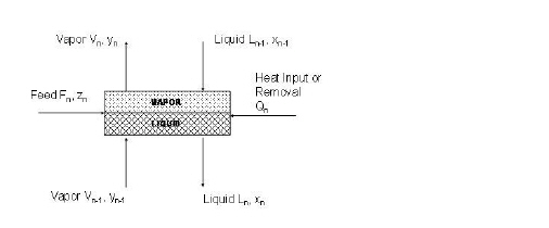
The distillation column model is based on an elementary “building” block called “stage” (a graphical representation of a stage is shown in the figure below). The stage model simulates an actual “stage” and is approximated with a CSTR model. The stage model has outgoing liquid and vapor streams with properties equal to those of the stage (P, T, x, y). For N components, there is a total of 2*N+4 unknowns and 2*N+3 equations for each stage (N vapor compositions, N liquid compositions, two flowrates, the heat exchanged and the temperature). For an adiabatic stage, the number of equations and the number of unknowns is equal to 2*N+3. The thermodynamic relationships are not counted as equations since the vaporization ratio and the enthalpies are not treated as unknowns (they are calculated separately once P, T, x and y have been estimated).
A graphical representation of a stage is shown below:
The following constitutive relationships are applied to each stage:
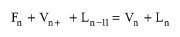
Total Mass Balance:
|
|
eq. (A.237) |
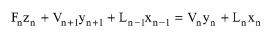
Component Mass Balance:
|
|
eq. (A.238) |
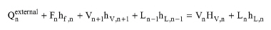
Energy Balance:
|
|
eq. (A.239) |
Equilibrium Relationship:
|
|
eq. (A.240) |
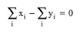
Continuity Equation:
|
|
eq. (A.241) |
Thermodynamic Model:
|
|
eq. (A.242) |
The simple distillation model used in SuperPro Designer is based on CSTR's in series. The model puts together the equations of each stage described earlier. The equations are based on principles of mass (total and component) and energy conservation and thermodynamic equilibrium. This set of equations is known as MESH equations (Mass, Energy, Summation and Enthalpy) and once they are solved, we can predict the behavior of the column. A graphical representation of a simple distillation model is shown in the figure below.
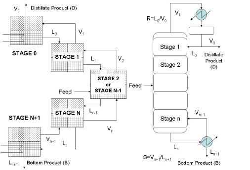
More specifically, the striping and rectifying sections of the column are modeled using ideal stages. The feed section is modeled using a feed stage and the reboiler section is modeled with a side product stage. The condenser section model varies with the condenser type. When the so-called total condenser is used, then a special model is employed as described later. When a partial condenser is used than a side product stage model is employed. In general, the distillation model of a column with M stages (including a reboiler and a condenser) has M*[2*N+3] equations and unknowns. The number of equations and unknowns might slightly change with the condenser and the reboiler type.
A very important property of the model is the so-called Number of Degrees of Freedom (NDF). Mathematically speaking, this is the difference between the total number of unknowns and the total number of equations. According to that, a mathematical solution is obtained only when the values of all NDF unknowns are specified. From the operating perspective, the Number of Degrees of Freedom is the number of “specifications” that the user must define in order to fully specify the operation of the unit. Typical specifications include the recycle rate, the raffinate to feed ratio, the condenser temperature, etc. It is important to emphasize that the “specifications” are additional conditions to model parameters such as the feed properties (pressure, temperature, overall composition), the column operating pressure and the number of stages.
Because all internal units are assumed adiabatic and thus, they have equal number of equations and unknowns, the total number of degrees of freedom is determined by the type of condenser and the type of reboiler. Furthermore, a typical partial reboiler (this is the only type currently supported by SuperPro Designer) contributes one degree of freedom because the reboiler is an ideal CSTR with heating.
A condenser on the other hand introduces additional degrees of freedom which vary with the type of condenser. More specifically:
● Total Condenser: A total condenser is simulated with a special model that introduces only one extra degree of freedom. This special model uses the facts that:
a) There is no composition change since the vapor feed is fully condensed to liquid.
b) The operating temperature and the cooling requirement is not considered an unknown since they are indirectly inferred by the vapor feed conditions and the bubble point operation assumption (no sub-cooling).
c) There is only one unknown which is the portion of liquid that is recycled to the stage.
As a result, a column with a total condenser is fully specified if the user provides two conditions:
a) The Raffinate/Feed ratio
b) The Recycle Ratio
● Partial Condenser. A partial condenser introduces two additional degrees of freedom which when added to the one provided by the reboiler it brings the total number of specifications required to three. More specifically, the partial condenser is a typical non-adiabatic stage with a liquid side stream (this stream is recycled to the column while the normal outlet liquid stream is the distillate). Thus, it introduces an additional degree of freedom from the heat exchange and an additional degree of freedom from the liquid side stream. As a result, a column with a partial condenser needs the following specifications:
a) The Raffinate/Feed ratio
b) The Recycle Ratio
c) The condenser temperature
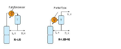
A graphical representation of a total condenser and a partial condenser is shown in the figure below.
The general methodology for solving the set of non-linear equations that model distillation column operation follows the steps below:
1. Problem setup
2. Initialization of variables
3. Root finding - convergence test
4. Output and engineering calculations (i.e. efficiency, column sizing, heating/cooling requirements).
Problem Setup
SuperPro Designer internally sets up the mathematical problem to be solved using the following process specifications:
1. Design Parameters. These include the number of stages and the feed location.
2. Design Specifications based on Condenser Type. For either a total or partial condenser, these include the raffinate/feed ratio and the recycle ratio. For a partial condenser, the condenser temperature is also required.
3. Column operating pressure.
4. Feed conditions: these include the flowrate, pressure, temperature, and composition of the feed.
Initialization of variables
SuperPro Designer initializes the variables (internal rates, temperatures and compositions) using the following methods:
● MANUAL: The user specifies all variables
● SEMI-MANUAL: A heuristic algorithm with a few parameters is used to provide values for the variables. The parameters of the heuristic can be either provided by the user or calculated internally by SuperPro Designer. The heuristic is based on the following principles:
1. Stage temperatures are initialized using feed temperature and condenser/ reboiler guesses
2. Stage compositions are initialized using feed compositions
3. Vapor internal flows are initialized using user provided guesses for the stripping and rectifying section
4. Liquid internal flows are calculated by solving the mass balance equations (using the vapor initial guesses).
Root Finding Method
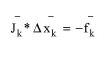
For the solution of the group of non-linear equations SuperPro Designer uses Newton-Raphson method as modified by Napthali-Sandholm. The method updates the current solution estimate using:
|
|
eq. (A.243) |
where:
● Jk is the Jacobian matrix evaluated using the values of the variables at the k-th iteration
● Δxk is the correction to the solution vector
● fk is the matrix of independent functions evaluated using the values of the variables at the k-th iteration
The model is formed for N components and M+2 stages (i.e., M internal stages, one recycle stage and one reboiler stage). The model variables consist of M stage temperatures (Tj), M total vapor flow rates (Vj), M total liquid flow rates (Lj), MxN component liquid compositions (xij), and MxN component vapor compositions (yij). The total number of variables in the model is M(2N+3).
The Jacobian matrix has entries that depend on the partial derivatives dH/dT, dH/dx, dH/dy, dK/dT, dK/dx, and dK/dy, which are calculated numerically based on finite differences. It is a sparse and block-banded matrix that has a lot of non-zero entries with values of -1, 1 and 0.
Modeling Challenges/ Heuristics for Solution Convergence
1. Initialization. The adapted Newton-Raphson method is sensitive to initialization and can be trapped when multiple solutions exist. It is widely used however for non-ideal systems and columns with a relatively small number of components and a lot of stages.
2. Thermodynamic model selection. The selection of the model can lead to convergence problems. It is recommended to first obtain a solution using an ideal equilibrium model (Raoult's Law) and then use the results as an initial guess for the full blown model.
3. Numerical derivatives of Enthalpy and Ki,j. For selected thermodynamic models discontinuities in K and enthalpy with respect to temperature and composition can lead to convergence problems. It is recommended to first obtain a solution using an ideal equilibrium model (Raoult's Law) and then use the results as an initial guess for the full blown model.
The user specifies feed conditions, column operating conditions and two additional specifications (usually the mole ratio of raffinate to feed and the recycle rate). Based on this information, the program solves the material and energy balances for each theoretical stage and for the entire column.
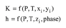
The user selects the thermodynamic model used to predict the K values. The K values express the tendency of a species to vaporize and effectively determine the separation efficiency of the column. The value of K for the i-th component is defined as:
|
|
eq. (A.244) |
where yi and xi are the mole fractions of the i-th component in the vapor and liquid phases, respectively.
The value of Ki is a function of system pressure, temperature and vapor and liquid compositions. There are three families of models available: Raoult's Law, γ-φ (gamma-phi) methods and EOS methods. The simplest model, known as Raoult's Law, assumes ideal liquid and vapor behavior and sets Ki = Pisat/ P where Pisat is the saturation pressure of pure component i at mixture temperature. Notice that Ki in this selection depends on temperature only.
For all methods provided it is possible to overwrite the Ki value predicted by the selected model using an empirical value. This value can be either a constant or a function of system temperature. This empirical capability allows prediction of column behavior when non-volatile (Ki=0) or non-condensable (Ki > >10) components exist in the feed. The user should be aware that this is an approximation which might provide solutions which are unrealistic.
The user also selects the two specifications: the molar ratio of raffinate-to-feed and the recycle rate (as a molar ratio).
The user must also specify if a total or a partial condenser will be used. The total condenser condensates the entire top column stream, recycles portion of the condensed liquid and outflows the rest. The partial condenser on the other hand, behaves like a typical separation tray. It condensates portion of the top column stream and outflows the remaining vapor. Finally, it recycles portion of the condensed liquid and outflows the rest. Notice that a distillation column with a total condenser has two outlet streams (one liquid distillate and one liquid raffinate). A distillation column with a partial condenser on the other hand has three outlet streams (one vapor distillate, one liquid distillate and on liquid raffinate). Notice that when selecting a partial condenser the user must specify condenser operating temperature.
Once the above parameters are specified, the system of equations that models the material and energy balance of each theoretical tray is solved simultaneously. The solution specifies the temperatures, the flowrates and the species compositions for all theoretical trays and for the top condenser and the bottom reboiler.
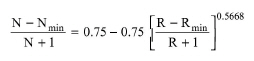
In Design Mode, the user specifies the desired reflux ratio (R) as a fraction of Rmin (R is usually 10-50% greater than Rmin) and the program calculates the number of theoretical stages (N) using Gilliland's (1940) correlation as expressed by Eduljee (1975):
|
|
The number of actual stages is calculated by dividing the number of theoretical stages by the stage efficiency. The actual number of stages times the stage height yields the height of the column. The column diameter is calculated by dividing the vapor flowrate by the vapor linear velocity that is specified by the user. If the calculated column diameter exceeds the maximum, the program assumes multiple units operating in parallel with a total cross sectional area equal to the calculated.
In Rating Mode, the user specifies the dimensions of the column and the stage efficiency and the program calculates the required reflux ratio.
1. Henry Z. Kister, Distillation Design, 1992
The interface of this operation has the following tabs:
● Oper. Cond’s, see Continuous Distillation (Rigorous): Oper. Conds Tab
● VLE Options, see The Rigorous PS Calculation Toolbox Dialog
● Initial Values, see Continuous Distillation (Rigorous): Initial Values Tab
● Results, see Continuous Distillation (Rigorous): Results Tab
● Numerics, see Flash Evaporation: Numerics Tab
● Labor, etc, see Operations Dialog: Labor etc. Tab
● Description, see Operations Dialog: Description Tab
● Batch Sheet, see Operations Dialog: Batch Sheet Tab
● Scheduling, see Operations Dialog: Scheduling Tab