In the case that the relative volatility of a component is calculated by the program, the user must specify a corresponding temperature, choosing the temperature at the top, the temperature at the bottom or the geometric mean (average) of the two.
Distillation is the workhorse separation unit in the process industries. This operation is used to separate the components of a mixture. In the biochemical industries, distillation is used in the recovery and purification of volatile compounds, such as ethanol and organic acids.
In a typical distillation unit, feed is provided near the middle of the vessel. On entrance, portion of the feed vaporizes and moves upward with the remaining liquid moving downwards. The unit uses a “boiler” (re-boiler) to vaporize portion of the liquid fluid that leaves the main vessel. The produced vapors re-enter the distillation drum and start to move upwards again. As they do so, they meet the downwards moving liquid stream, cool down and lose the heavy components via condensation. When they vapors reach the top of the column, they exit the vessel and become fully (or partially) condensed in the “condenser”. Portion of the condensed vapors re-enter the column and become the downward moving liquid referred to earlier. The other portion exits the distillation column as a product stream. Two physical (mass transfer) phenomena take place inside the column vessel. The “stripping” of light components from the liquid phase and the condensing of heavy components from the vapor phase. Both of them are needed for the separation. Furthermore, they are enhanced through the use of special equipment called “plates”. The plates are designed to increase the “multi-phase contact” and mass transfer efficiency. The overall separation efficiency of the column depends on the hardware configuration and on the relative volatility of species.
There are two major types of distillation columns, Simple and Complex:
● Simple columns have only one feed, a top product and a bottom product (no side products). The column has a top condenser and a bottom reboiler but no interreboiler or intercondensers
● Complex columns have more than one feed, one or more side products and sometimes interreboilers, intercondensers, pumparrounds and sidestreams
Currently, SuperPro Designer supports simulation of simple columns. In future releases, simulation of complex columns will be included.
The design of a distillation column is a trial and error procedure that looks for a hardware configuration that achieves the desired separation efficiency. Given the large number of available options (reboiler types, condenser types, number of plates, operating pressure, recycle rate, feed pre-heating, etc.) it is critical to have a mathematical model that is able to accurately and efficiently predict the expected separation efficiency of any hardware configuration. There are various mathematical models available in the literature. The simple models are the so-called short-cut models which are semi-empirical in nature and provide easy solutions at the cost of low accuracy. The more sophisticated models are based on rigorous VLE calculations and provide high accuracy predictions at the cost of higher complexity.
This operation employs a semi-empirical shortcut model (i.e., the Fenske-Underwood-Gilliland method) to obtain an estimate of the number of theoretical stages that are required for a specified separation. In addition, it provides a rough estimate of the condenser and reboiler temperatures and the respective associated thermal loads. For a more elaborate design of a Distillation Column, see Continuous Distillation (Rigorous).
● Continuous (Short-Cut) Distillation Procedure
The user specifies the percentage of each component that ends up in the distillate. Based on this information, the program calculates the overall material balances.
Energy Balances
While the original Fenske-Underwood-Gilliland method does not account for energy balances, the model provides a rough estimation of the condenser and reboiler thermal requirements under the following assumptions:
● The top stream entering the condenser is all-vapor at the weighted-average boiling point of its components.
● The condenser operates at that exact temperature, unless its temperature is set by the user.
● After the condenser, all components except the non-condensables are assumed to be 100% in the liquid phase.
● The condenser thermal duty is calculated as the load required to bring the top stream from its vapor state at the temperature upstream the condenser to its liquid state at the temperature of the condenser.
● The bottom stream exiting the reboiler is all-liquid at the weighted-average boiling point of its components.
● The reboiler operates at that exact temperature, unless its temperature is set by the user.
● The thermal duty of the reboiler is estimated by the energy balance around the column.
Initially, the user must specify the component molar percentages in the distillate stream and identify the light and heavy key components. The relative volatilities (ai) w.r.t the heavy key component can either be automatically calculated by the program or be specified by the user.
|
|
In the case that the relative volatility of a component is calculated by the program, the user must specify a corresponding temperature, choosing the temperature at the top, the temperature at the bottom or the geometric mean (average) of the two. |
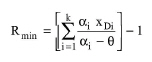
Notice that in order for a component to have its relative volatility automatically calculated, its percentage in the distillate must be non-zero. The minimum reflux ratio (Rmin) is estimated using the second Underwood equation (Underwood 1948):
|
|
eq. (A.232) |
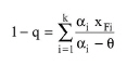
where k is the number of components, XDi is the mole fraction of component i in the distillate, and θ is determined from the solution of the first Underwood equation:
|
|
eq. (A.233) |
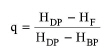
where XFi is the mole fraction of component i in the feed and q is the quality of the feed:
|
|
eq. (A.234) |
HDP, HBP and HF are the enthalpies of the feed as saturated vapor, the feed as saturated liquid, and the actual feed, respectively. In other words, q expresses the percentage of latent heats of vaporization, λ = HDP - HBP, that are required so the feed becomes saturated vapor. Regarding the quality of feed, there are five alternatives (Assael and Magilliotou, 1998):
|
Feed quality (physical state) |
|
q |
|
|
||
|
Subcooled liquid |
HF < HBP < HDP |
>1 |
|
Saturated liquid |
HF = HBP < HDP |
1 |
|
Vapor/liquid mixture |
HBP < HF < HDP |
(0, 1) |
|
Saturated vapor |
HBP < HF = HDP |
0 |
|
Superheated vapor |
HBP < HDP < HF |
< 0 |
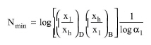
Next, the program estimates the minimum number of stages (Nmin), using the correlation proposed by Fenske (1932):
|
|
eq. (A.235) |
where the subscripts l and h denote the light and heavy key components while D and B denote distillate and bottom.
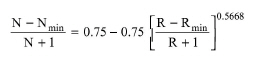
In Design Mode, the user specifies the desired reflux ratio (R) as a fraction of Rmin (R is usually 10-50% greater than Rmin) and the program calculates the number of theoretical stages (N) using Gilliland's (1940) correlation as expressed by Eduljee (1975):
|
|
The number of actual stages is calculated by dividing the number of theoretical stages by the stage efficiency. The actual number of stages times the stage height yields the height of the column. The column diameter is calculated by dividing the vapor flowrate by the vapor linear velocity that is specified by the user. If the calculated column diameter exceeds the maximum, the program assumes multiple units operating in parallel with a total cross sectional area equal to the calculated.
In Rating Mode, the user specifies the dimensions of the column and the stage efficiency and the program calculates the required reflux ratio.
1. Underwood, A.J.V., (1948), Chem. Eng. Prog., 44, p. 603.
2. Gilliland, E.R., (1940), Ind. Eng. Chem., 32, p. 1101.
3. Eduljee, H.E., (1975), Hydro. Proc., 54(9), p. 120.
4. Assael M.J. and Magilliotou M., Introduction to Unit Operations, Aristotle University Publications, Thessaloniki, Greece (1988) (in Greek).
The interface of this operation has the following tabs:
● Oper. Cond’s, see Continuous Distillation (Shortcut): Oper. Conds Tab
● Component Separation, see Continuous Distillation (Shortcut): Comp. Separation Tab
● Labor, etc, see Operations Dialog: Labor etc. Tab
● Description, see Operations Dialog: Description Tab
● Batch Sheet, see Operations Dialog: Batch Sheet Tab
● Scheduling, see Operations Dialog: Scheduling Tab