eq. (A.140)
Cyclone collectors are used for the separation and recovery of particulate matter from air or process gases. Their use is recommended for particles with diameters greater than 5 µm.
● Centrifugation in a Gas Cyclone Procedure
The removal efficiency for particles in the feed stream is either specified by the user or calculated by the model. The rest of this section describes the algorithm for the calculation of the removal efficiency by the model.
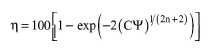
The efficiency for each particle size is calculated based on the model proposed by Leith and Licht (1972):
|
|
eq. (A.140) |
where C is a dimensionless design number that depends upon the physical shape of the cyclone and is defined as:
|
|
eq. (A.141) |
where Kc is the cyclone volume constant. Also, Ka = a/D and Kb = b/D, where D is the cyclone body diameter, a is the inlet height of the cyclone, and b is the inlet width of the cyclone.
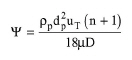
In addition, Ψ is a dimensionless impaction parameter that depends upon the operating conditions in the cyclone and is defined as:
|
|
eq. (A.142) |
where ρp is the particle density, dp is the particle diameter, μ is the gas viscosity, n is the dimensionless exponent of the vortex law for tangential velocity distribution, and uT is the tangential particle velocity. The tangential velocity of the particles is defined as:
|
|
eq. (A.143) |
where Q is the volumetric flowrate of the gas through the cyclone.
The overall cyclone removal efficiency is the sum of the products of the removal efficiency for each particle size times the weight fraction of that particle size. The weight fractions for each particle size are defined in the particle size distribution.
All the geometrical design characteristics of the cyclone are related to the body diameter D, based on the optimal proportions proposed by Lapple and Sepherd (1939, 1940) which follow:
● Inlet width, b = D/4.
● Gas outlet diameter, De = D/2.
● Inlet height, a = D/2.
● Height of upper cylindrical body, h = 2D.
● Outlet length, S = 5D/8.
● Overall cyclone height, H = 4D.
● Outlet duct diameter for dust, B = D/4.
The Power corresponds to the total power consumption by this operation (for fanning, etc.) If the corresponding Set by User option is not selected, then the Power is calculated by the program as Qtot ΔP / e, where e is the total power efficiency (the ratio of ideal to actual power consumption for fanning, etc.).
1. Leith, D. and W. Licht (1972). AIChE Symposium Series, 68(126).
2. Lapple, C.E. and C. B. Shepherd (1939). Ind. Eng. Chem., 31(8).
3. Lapple, C.E. and C. B. Shepherd (1940). Ind. Eng. Chem., 32(9).
The interface of this operation has the following tabs:
● Oper. Cond’s, see Centrifugation in a Gas Cyclone: Oper. Conds Tab
● Part. Removal, see Centrifugation in a Gas Cyclone: Part. Removal Tab (Set By User) and Centrifugation in a Gas Cyclone: Part. Removal Tab (Calculated)
● Labor, etc, see Operations Dialog: Labor etc. Tab
● Description, see Operations Dialog: Description Tab
● Batch Sheet, see Operations Dialog: Batch Sheet Tab
● Scheduling, see Operations Dialog: Scheduling Tab