This model is used to simulate continuous countercurrent leaching (or solids extraction) in a series of mixing-settling units (or stages). In leaching, a liquid solvent is used to dissolve soluble matter from its mixture with an insoluble solid. Continuous countercurrent leaching is used when the solid is impermeable or when it disintegrates during leaching. In this case, the solids are dispersed in the solvent by mechanical agitation in a mixing tank or flow mixing and the leached residue is separated from the strong solution by settling.This process is frequently used in the food industry for extraction of vegetable oils, sugar, instant coffee, but also in pharmaceutical industry for extraction of active ingredients from plants.
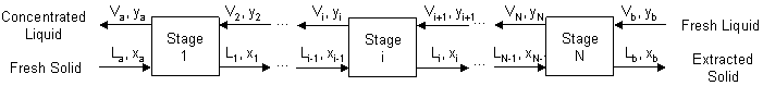
The figure below shows a schematic representation of a continuous countercurrent cascade consisting of multiple extraction stages:
where:
● La is the flow of solution in the fresh solid entering the system through the first stage,
● xa is the mass fraction of solute in solution La,
● Va is the flow of solution in the concentrated liquid leaving the first stage,
● ya is the mass fraction of solute in solution Va,
● Lb is the flow of solution in the extracted solid leaving the final stage,
● xb is the mass fraction of solute in solution Lb,
● Vb is the flow of solution in the fresh liquid entering the system through the final stage,
● yb is the mass fraction of solute in solution Vb,
● N is the number of stages,
● Li is the flow of solution in the solid leaving stage i (i=0, 1, ..., N; L0=La; LN=Lb) (solution underflow),
● xi is the mass fraction of solute in solution Li (i=0, 1, ..., N; x0=xa; xN=xb),
● Vi is the flow of solution in the liquid leaving stage i (i=1, 2, ..., N+1; V1=Va; VN+1=Vb) (solution overflow), and
● yi is the mass fraction of solute in solution Vi (i=1, 2, ..., N+1; y1=ya; yN+1=yb).
Stages are numbered in the direction of flow of the solid. Fresh solid is fed at stage 1 and exhausted solid leaves stage N. Fresh liquid is fed at stage N and concentrated liquid overflows from stage 1. The liquid overflows from stage to stage in a direction counter to that of the flow of the solid, dissolving solute as it moves from stage N to stage 1. It is assumed that a fraction of this solution (solution overflow) remains on the solid and exits through the underflow (solution underflow). Additional assumptions are as follows:
1. The solute-free solid (carrier) components are insoluble in the liquid solvent components. However, some solid flakes may still be carried away with the solvent. For convenience, the user can specify a fraction of carrier that is lost in the liquid phase. However, it is assumed that this can only happen in the first stage. The flow of carrier is assumed constant throughout the rest of the cascade.
2. The stage efficiency is assumed equal to one. Therefore, the number of stages is equal to the number of ideal stages. In an ideal stage, the requirements for equilibrium are met. Provided sufficient solvent is present to dissolve all the solute in the entering solid (i.e., concentration is less than solubility) and there is no adsorption of solute by the solid, equilibrium is attained when the solute is completely dissolved and the concentration of the solution so formed is uniform. Then, the concentration of the solution retained by the solid leaving any stage is the same as that of the solution overflow from the same stage.
3. The density and viscosity of the solution underflow do not change considerably with solute concentration in stages 2 to N. Therefore, the solution underflow is assumed constant in these stages.
The overall material balance of component j can be written as:
|
|
where:
● k is an index denoting the component classification type (‘n’ for none, ‘c’ for carrier, ‘s’ for solvent and ‘p’ for solute),
● Lk,j,a is the flow of type k component j in the fresh solid entering the first stage,
● Lk,j,b is the flow of type k component j in the extracted solid leaving the final stage,
● Vk,j,a is the flow of type k component j in the concentrated liquid leaving the first stage, and
● Vk,j,b is the flow of type k component j in the fresh liquid entering the final stage.
The values of Lk,j,a and Vk,j,b are determined based on the flow and composition of the two input streams and on the specified classification type for each component. The values of Lk,j,b and Vk,j,a are calculated by solving eq. (A.250) and another equation that depends on the classification type of component j and uses a measure of component recovery in the liquid phase.
For carrier component j, the fraction, fc,j, of this component in the fresh solid entering the system that is lost in the liquid phase leaving the system is defined as:
|
|
where:
● Lc,j,a is the flow of carrier component j in the fresh solid entering the first stage,
● Lc,j,b is the flow of carrier component j in the extracted solid leaving the final stage,
● Lc,j,i is the flow of the carrier component in the solid leaving stage i (i=1, 2, ..., N; Lc,N = Lc,b), and
● fc,j is the fraction of Lc,j,a that is lost in the liquid phase leaving the first stage.
Two specification options are available for specifying fc,j:
● Same As Total Carrier Loss in Liquid Phase
● Set By User (Per Component)
If the first option is selected, then the total carrier loss fraction in the liquid phase, fc,tot, is specified and fc,j is set equal to fc,tot for all carrier components. The fraction fc,tot is defined as:
|
|
where:
● fc,tot is the total carrier loss fraction in the liquid phase leaving the first stage,
● Lc,tot,a is the total flow of all carrier components in the solid phase entering the first stage, and
● Lc,tot,b is the total flow of all carrier components in the solid phase leaving the final stage.
If the second option is selected, then fc,j is set by user for each carrier component and fc,tot is calculated using eq. (A.252).
For a solute component j, the fraction, fp,j, of this component in the fresh solid entering the system that is recovered in the liquid phase leaving the system is defined as:
|
|
eq. (A.253) |
where:
● Lp,j,a is the flow of solute component j in the fresh solid entering the first stage,
● Lp,j,b is the flow of solute component j in the extracted solid leaving the final stage, and
● fp,j is the fraction of Lp,j,a that is recovered in the liquid phase leaving the first stage.
Two specification options are available for specifying fp,j:
● Same As Total Solute Recovery Yield in Liquid Phase
● Set By User (Per Component)
If the first option is selected, then the total solute recovery yield in the liquid phase, fp,tot, is specified and fp,j is set equal to fp,tot for all solute components. The fraction fp,tot is defined as:
|
|
where:
● fp,tot is the total solute recovery yield in the liquid phase, and
● Lp,tot,a is the total flow of all solute components in the solid phase entering the first stage, and
● Lp,tot,b is the total flow fo all solute components in the solid phase leaving the final stage.
If the second option is selected, then fp,j is set by user for each solute component and fp,tot is calculated using eq. (A.254).
For a solvent component j, the fraction, fs,j, of this component in the fresh liquid entering the system that is lost in the solid phase leaving the system is defined as:
|
|
eq. (A.255) |
where:
● Vs,j,a is the flow of solvent component j in the extracted liquid leaving the first stage,
● Vs,j,b is the flow of solvent component j in the fresh liquid entering the final stage, and
● fs,j is the fraction of Vs,j,b that is lost in the solid phase leaving the final stage.
Two specification options are available for specifying fs,j:
● Calculated Based On Total Solvent Loss In Solid Phase, and
● Calculated Based On Amount of Retained Solution In Solid Phase.
If the first option is selected, then the total solvent loss in the liquid phase, fs,tot, is specified and fs,j is set equal to fs,tot for all solvent components. The fraction fs,tot is defined as:
|
|
where:
● fs,tot is the total solvent loss fraction in the solid phase leaving the final stage,
● Vs,tot,a is the total flow of all solvent components in the liquid phase leaving the first stage, and
● Vs,tot,b is the total flow of all solvent components in the liquid phase entering the final stage.
Then, the ratio, r, of the amount of retained solution to the amount of carrier in the solid phase can be calculated. This is defined as:
|
|
where:
● r is the ratio of the amount of retained solution to the amount of carrier in the solid phase,
● Ls,tot,b is the total solvent flow in the liquid phase leaving the final stage, and
● xtot,b is the total solute mass fraction in the liquid phase leaving the final stage.
If the second option is selected, then the ratio r is specified and fs,tot is calculated by solving the system of eq. (A.250), eq. (A.256) and eq. (A.257). Subsequently, fs,j is set equal to fs,tot for all solvent components.
In order for the combination of fp,j and fs,j values to be valid, this model requires that the amount of solution underflow leaving the system is greater than the amount of solution entering the system minus the amount of recovered solute in the liquid phase leaving the system:
|
|
eq. (A.258) |
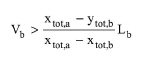
Also, in order to have a positive driving force for leaching, this model requires that the solution overflow is greater than the one corresponding to zero leaching:
|
|
eq. (A.259) |
In Design Mode, the sizing of the mixer and settler tanks is based on the corresponding residence times in the mixer and settler, respectively, which are specified by the user. If the operating (rated) throughput exceeds the maximum, the program assumes multiple units operating in parallel with a total throughput equal to the calculated one.
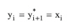
In addition, the number of ideal stages of the mixer-settler extractor is calculated based on a reference solute component (the selected “Main Solute”). This is determined by solving the system of equilibrium equation, operating equation (main solute material balance) and solution material balance in each stage. According to the second assumption of this model, the following equation is valid when the solid and liquid phases leaving stage i are in equilibrium:
|
|
where:
● yi is the mass fraction of solute in the liquid phase leaving stage i (i=1, 2, ..., N),
● y*i+1 is the equilibrium mass fraction of solute in the liquid phase leaving stage i (i=1, 2, ..., N), and
● xi is the mass fraction of solute in the solid phase leaving stage i (i=1, 2, ..., N).
Therefore, y*a = xa and y*b = xb .
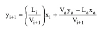
The equation for the operating line is obtained by writing the main solute material balance for that portion of the cascade consisting of the first i units:
|
|
eq. (A.261) |
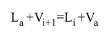
Also, the solution material balance for the first i units is:
|
|
When the solution underflow is constant, there are two possibilities:
If the ratio Lb/Vb is equal to 1.0, then the equilibrium y-x line and the operating y-x line are parallel and the driving force of leaching is constant throughout the cascade. Then, the number of ideal stages is simply calculated as the ratio between the overall change in the mass fraction of solute and the driving force of leaching:
|
|
eq. (A.263) |
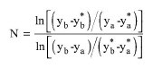
If the ratio Lb/Vb is not equal to 1.0, then the number of ideal stages can be calculated using the following equation:
|
|
If the solution entering with the fresh solids (La) differs from the solution underflow within the system (Lb), the performance of the first stage is calculated separately by applying eq. (A.260)-eq. (A.262) to the first stage, and then eq. (A.264) is applied to the remaining stages (i.e., subscript "a" is substituted with "1").
Three thermal modes of operation are available: Set Temperature (isothermal), Adiabatic, Set Heating or Cooling Duty. In the isothermal case, the program calculates the required heating or cooling duty. In the other two cases, it calculates the operating temperature. If the operation is not adiabatic, the specified percentage of power consumption that dissipates into heat also contributes to the heating or cooling requirements of the step.
In terms of power consumption, the following specification options are available:
a) Set Specific Power
b) Set Total Power
c) Set Power Per Unit
If option (a) is selected, the power consumed per mixer volume is specified and the total power and power per unit are calculated. If option (b) is specified, the total power consumed by the operation is specified and the specific power and power per unit are calculated. If option (c) is selected, the power consumed per equipment unit is specified and the specific power and total power are calculated.
If the thermal mode of operation is not set to adiabatic, it is assumed that a specified percentage of total power consumption eventually dissipates into heat that contributes to the heating or cooling requirements of the step.
1. McCabe W. L., J. C. Smith and P. Harriott (1993). Unit Operations of Chemical Engineering, McGraw-Hill.
2. R.E. Treybal, Mass-Transfer Operations, McGraw-Hill.
The interface of this operation has the following tabs:
● Oper. Cond’s, see Solids Leaching: Oper. Conds Tab
● Mat. Balance, see Solids Leaching: Material Balance Tab
● Labor, etc, see Operations Dialog: Labor etc. Tab
● Description, see Operations Dialog: Description Tab
● Batch Sheet, see Operations Dialog: Batch Sheet Tab
● Scheduling, see Operations Dialog: Scheduling Tab